Method and system used for detecting metal material fatigue state

A metal material, fatigue state technology, applied in the direction of material analysis using sonic emission technology, can solve problems such as uncertainty in the expansion direction, and achieve the effect of ensuring personal safety and saving costs

Inactive Publication Date: 2013-01-02
BEIJING INSTITUTE OF TECHNOLOGYGY
View PDF3 Cites 21 Cited by
  • Summary
  • Abstract
  • Description
  • Claims
  • Application Information

AI Technical Summary

Problems solved by technology

However, due to various defects on the surface or inside of the actual part, under the loading of cyclic stress, micro-cracks may

Method used


Image

  • Method and system used for detecting metal material fatigue state
  • Method and system used for detecting metal material fatigue state
  • Method and system used for detecting metal material fatigue state

Examples


Embodiment Construction

[0019] A method and system for detecting the fatigue state of metal materials provided by the present invention will be described in detail below with reference to the accompanying drawings and specific embodiments.

[0020] In the following description, various aspects of the present invention will be described. However, those skilled in the art can implement the present invention by using only some or all of the structures or processes of the present invention. For clarity of explanation, specific numbers, arrangements and sequences are set forth, but it will be apparent that the invention may be practiced without these specific details. In other instances, well-known features have not been described in detail in order not to obscure the invention.

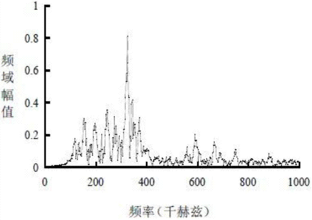
[0021] In order to eliminate the influence of interference noise on the real fatigue signal to a greater extent, the present application distinguishes the noise signal from the fatigue signal in the frequency domain. Among them...


PUM


Abstract

The invention provides a method and a system used for detecting a metal material fatigue state. According to the invention, an acoustic emission sensor is adopted; acoustic emission voltage signals released by fatigue metal material are acquired; acquired acoustic emission energy signals are converted into energy accumulation within a specific frequency range; a fatigue state is converted according to the energy accumulation within the specific frequency range; and service life forecast is obtained.

Description

technical field [0001] The present invention relates to metal detection technology, more specifically, to a method and system for detecting the fatigue state of metal materials. Background technique [0002] Under the long-term action of variable stress and strain, the fracture phenomenon caused by cumulative damage of metal components is called fatigue. Many parts in actual work work under variable loads. In fact, most of the damage of auto parts is caused by fatigue, and 60%-80% of the fractures in aerospace engineering are caused by fatigue damage of structural materials. Fatigue problems not only appear in machinery, aerospace, civil engineering and other departments, but also in almost all engineering fields such as nuclear engineering and water and land transportation. [0003] At present, as a new dynamic non-destructive testing method, acoustic emission technology has been widely used in industries such as aerospace, bridges, materials, and geology. The phenomenon ...

Claims


Application Information

Patent Timeline
IPC IPC(8): G01N29/14
Inventor 黄杰毕路拯石鹏飞
Owner BEIJING INSTITUTE OF TECHNOLOGYGY
Why Eureka
Try Eureka