Nested disc cam focusing mechanism

A disc cam, nested technology, used in installation, optics, instruments, etc., can solve the problems of machining and assembly errors, cam groove crossing, large errors, etc., to avoid coupling linkage, eliminate return errors, and avoid gaps. Effect

Inactive Publication Date: 2013-01-02
CHANGCHUN INST OF OPTICS FINE MECHANICS & PHYSICS CHINESE ACAD OF SCI
View PDF5 Cites 10 Cited by
  • Summary
  • Abstract
  • Description
  • Claims
  • Application Information

AI Technical Summary

Problems solved by technology

As the number of nesting layers increases, the number of nesting layers of the lens barrel or lens base will increase exponentially, and there will be processing and assembly errors in each nesting layer. If this continues, the error will become larger and larger until it cannot be achieved. Meet the accuracy requirements of the system
Moreover, as the number of nesting layers increases, the number of cam grooves required will also increase accordingly. If all the cam grooves are processed on the same lens barrel, there may be a phenomenon that the cam grooves cross, making it impossible to achieve Accurate focusing of individual nested layers
[0004] Furthermore, in order to allow the roller or follower to rotate flexibly in the cam groove, the width of the cam groove should be slightly larger than the diameter of the roller, which will cause a gap between the cam groove and the roller, which will affect the focusing accuracy
Although there are currently some measures that can theoretically eliminate the gap between the cam groove and the roller, this will undoubtedly increase the overall complexity of the mechanism, increase the processing cost and the difficulty of assembly and adjustment

Method used


Image

  • Nested disc cam focusing mechanism
  • Nested disc cam focusing mechanism
  • Nested disc cam focusing mechanism

Examples


Embodiment Construction

[0016] Below in conjunction with accompanying drawing, the present invention is described in further detail:

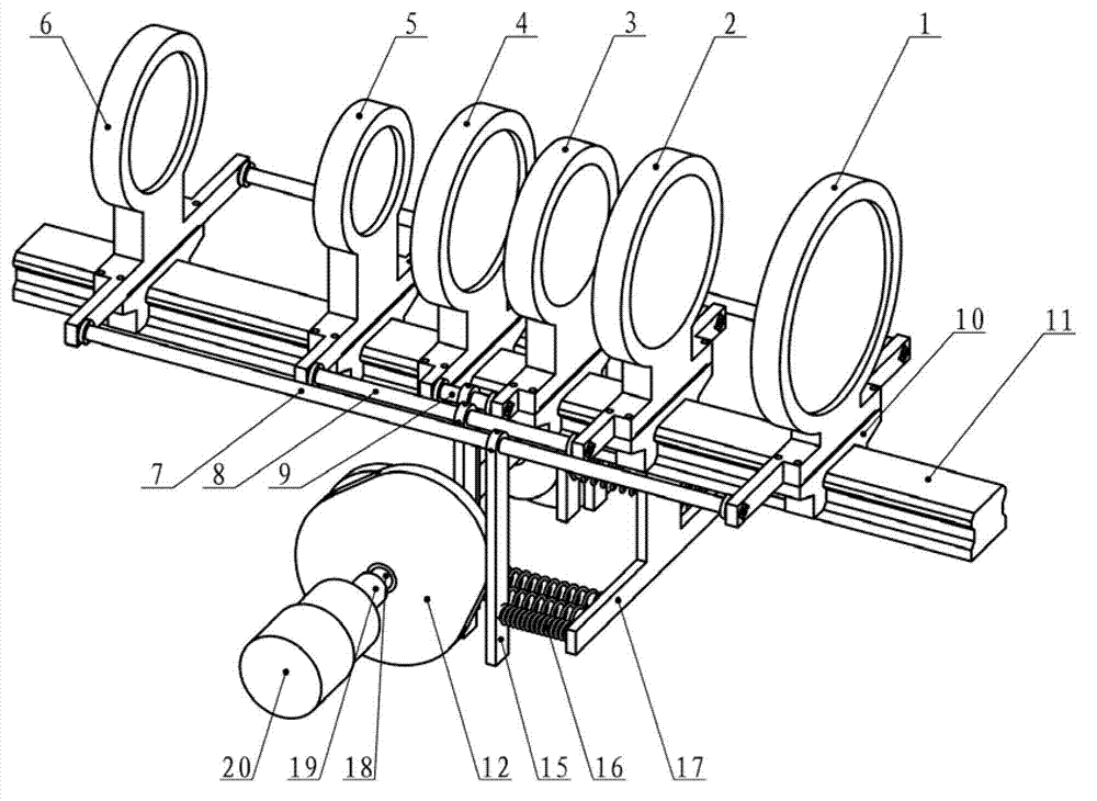
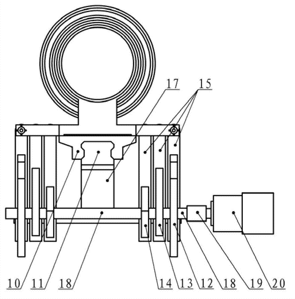
[0017] Such as figure 2 , image 3 , Figure 4 , Figure 5 As shown, the nested disc cam focusing mechanism includes: the first mirror mount 1, the second mirror mount 2, the third mirror mount 3, the fourth mirror mount 4, the fifth mirror mount 5, and the sixth mirror mount 6 , the first connecting rod 7, the second connecting rod 8, the third connecting rod 9, the slider 10, the guide rail 11, the first cam 12, the second cam 13, the third cam 14, the follower 15, the spring 16, the spring Block plate 17, camshaft 18, coupling 19, motor 20. The relative position between the first mirror base 1 and the sixth mirror base 6 remains unchanged, forming the first mirror base group; the relative position between the second mirror base 2 and the fifth mirror base 5 remains unchanged, forming the second mirror base group. Mirror base group; the relative position betwe...


PUM


Abstract

The invention discloses a nested disc cam focusing mechanism, belonging to the field of cam focusing. The nested disc cam focusing mechanism provided by the invention solves the problems that a focusing mechanism of a nested optical system is complicated, the focusing precision is low and the like. The mechanism mainly comprises a first microscope base, a second microscope base, a third microscope base, a fourth microscope base, a fifth microscope base, a sixth microscope base, a slider, a guide rail, disc cams, a driven member, a spring and the like, wherein the first microscope base and the sixth microscope base form a first microscope base group; the second microscope base and the fifth microscope base form a second microscope base group; the third microscope base and the fourth microscope base form a third microscope base group; the microscope base groups move relatively along the direction of an optical axis to form a nested structure; three disc cams control the moving rules of the three groups of nested microscope bases through the driven member respectively and change the positions of the three groups of nested microscope bases so as to realize focusing of the whole system; and moreover, due to the independent microscope base and disc cam structure, compared with a cylindrical cam, the structure is simple, the processing cost is low, and the focusing precision is high.

Description

technical field [0001] The invention belongs to the field of cam focusing. Background technique [0002] Usually, the lens is circular, and the corresponding lens holder or lens barrel used to assemble and fix the lens is also circular. In order to make the structure simple and compact, easy to process, and to ensure the coaxiality between lenses and various matching tolerances, cylindrical cams are mostly used in the field of cam focusing. However, in some optical focusing systems, the use of cylindrical cam structures has its limitations. [0003] Such as figure 1 In the shown optical system, lenses a and f constitute the first lens group, lenses b and e constitute the second lens group, and lenses c and d constitute the third lens group. When focusing, the first and third lens groups move to the left, the second lens group moves to the right, and the six lenses form a triple nested structure. for something like figure 1 As shown in the nested optical system, it will ...

Claims


Application Information

Patent Timeline
Patent Type & Authority Applications(China)
IPC IPC(8): G02B7/10
Inventor 李小虎
Owner CHANGCHUN INST OF OPTICS FINE MECHANICS & PHYSICS CHINESE ACAD OF SCI
Why Eureka
Try Eureka