Finite-element analysis method for thermal mechanical strength of exhaust manifold

An exhaust manifold and analysis method technology, applied in special data processing applications, instruments, electrical digital data processing, etc., can solve problems affecting work reliability, improve temperature calculation accuracy, shorten development cycle, and improve calculation accuracy degree of effect

Active Publication Date: 2013-01-02
CHERY AUTOMOBILE CO LTD
View PDF5 Cites 18 Cited by
  • Summary
  • Abstract
  • Description
  • Claims
  • Application Information

AI Technical Summary

Problems solved by technology

The temperature and distribution of the exhaust manifold have a very important impact on its thermal stress and thermal strain, which in turn affects its working reliability

Method used


Image

  • Finite-element analysis method for thermal mechanical strength of exhaust manifold
  • Finite-element analysis method for thermal mechanical strength of exhaust manifold

Examples


Embodiment Construction

[0037] The present invention will be described in detail below according to the accompanying drawings, which is a preferred embodiment among various implementations of the present invention.

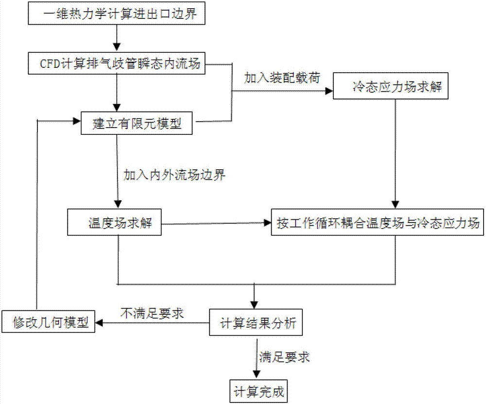
[0038] The finite element analysis method for the thermomechanical strength of the exhaust manifold includes the following steps:

[0039] Step a: One-dimensional thermodynamic boost calculation to obtain the boundary conditions at the inlet and outlet of the exhaust manifold under rated conditions (inlet flow, temperature; outlet pressure, temperature)

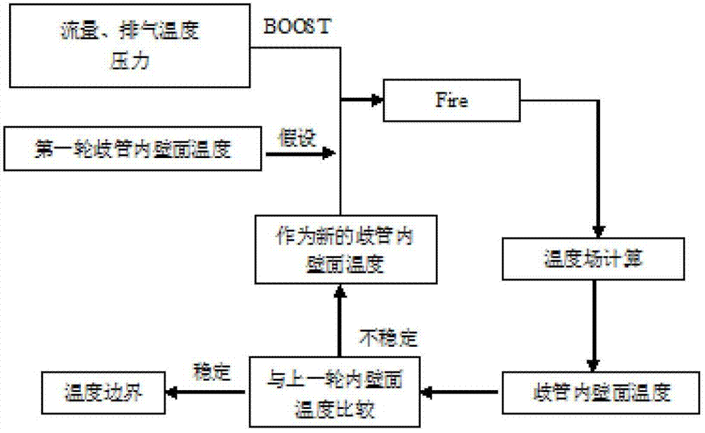
[0040] Step b: According to the boundary obtained by one-dimensional thermodynamic calculation, the flow field in the exhaust manifold under one working cycle is calculated by 3-dimensional CFD (Fire), and the temperature and convective heat transfer coefficient of the inner wall of the manifold are obtained.

[0041] Step c: Divide the finite element mesh according to the exhaust manifold assembly model

[0042] Step d: Calculate the ...


PUM


Abstract

The invention discloses a finite-element analysis method for thermal mechanical strength of an exhaust manifold, and aims to shorten the development period, reduce the development cost and perform virtual simulation on the mechanical performance and the structural reliability of an engine exhaust manifold in a digital model stage of the engine. By the method, the temperature field and a stress field of the engine exhaust manifold are calculated and solved by a finite-element method, so that temperature distribution, stress distribution, strain distribution, stud moment change and sealing pressure on the flange surface of the exhaust manifold of the engine exhaust manifold are obtained; and the structure of the engine exhaust manifold can be well designed.

Description

technical field [0001] The invention relates to an engine exhaust system, in particular to a finite element analysis method for the thermomechanical strength of an engine exhaust manifold. Background technique [0002] The engine exhaust system plays a decisive role in the overall performance of the engine. The exhaust manifold connects the cylinder head exhaust passage and the exhaust system, and is responsible for timely and smooth transmission of the high-temperature exhaust of the engine to the subsequent exhaust system, which can withstand high-temperature gases for a long time. The erosion, the working environment is quite harsh. The temperature and distribution of the exhaust manifold have a very important impact on its thermal stress and thermal strain, which in turn affects its working reliability. Fast and accurate calculation and analysis of the temperature field, through the calculation of thermal stress and thermal strain, to find out the area where thermal cra...

Claims


Application Information

Patent Timeline
Patent Type & Authority Applications(China)
IPC IPC(8): G06F17/50
Inventor 周君王成陈馨
Owner CHERY AUTOMOBILE CO LTD
Why Eureka
Try Eureka