Dipole antenna

A technology of dipole antennas and wires, which is applied in the direction of resonant antennas, antenna support/installation devices, antenna grounding switch structures, etc., can solve the problems of reducing the quality of dipole antennas, difficult welding, and prone to false welding, etc., to achieve The amount of solder is easy to control, the difficulty of soldering is reduced, and the effect of improving production efficiency

Active Publication Date:
View PDF5 Cites 2 Cited by
  • Summary
  • Abstract
  • Description
  • Claims
  • Application Information

AI Technical Summary

Problems solved by technology

The signal line of the coil and the wire is connected through a copper column, and the coil and the copper column are generally riveted, and the signal line of the wire and the copper column are generally welded; the dipole antenna with this structure, because the copper column is a hollow through hole, The signal line of the wire is welded in the center hole of the copper column. Since the solder is connected to the center hole of the wire and the copper column, it is difficult to weld, and it is prone to false welding and false welding, which affects the dipole. The stability of the transmitting frequency of the antenna even reduces the quality of the dipole antenna
In addition, in the dipole antenna of the prior art, the coil is sleeved in the sheath to protect the coil from damage and collision, but there is a gap between the top of the coil and the sheath. direction, due to the action of force, the coil will shake in the sheath. During the shaking of the coil, the frequency of the signal transmitted by the antenna is unstable, which not only affects the transmission frequency of the wireless communication device using this dipole antenna, but also affects the The stability of the signal received by the receiving device

Method used


Image

  • Dipole antenna
  • Dipole antenna
  • Dipole antenna

Examples


Embodiment Construction

[0021] The present invention is described in detail below in conjunction with accompanying drawing:

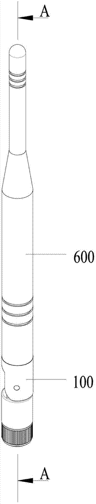
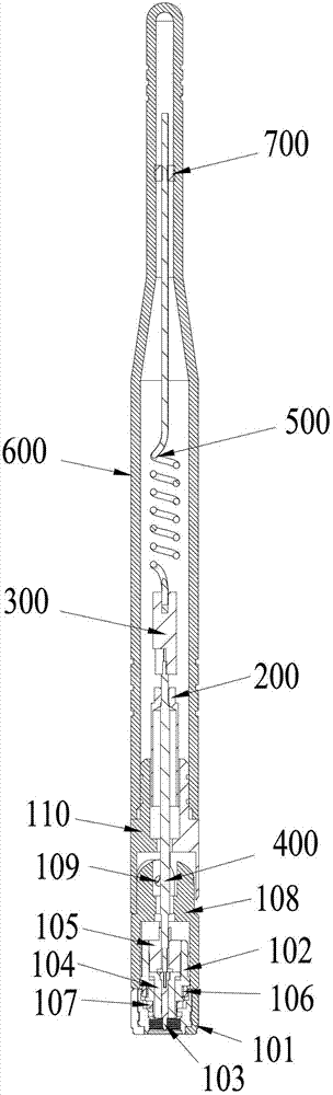
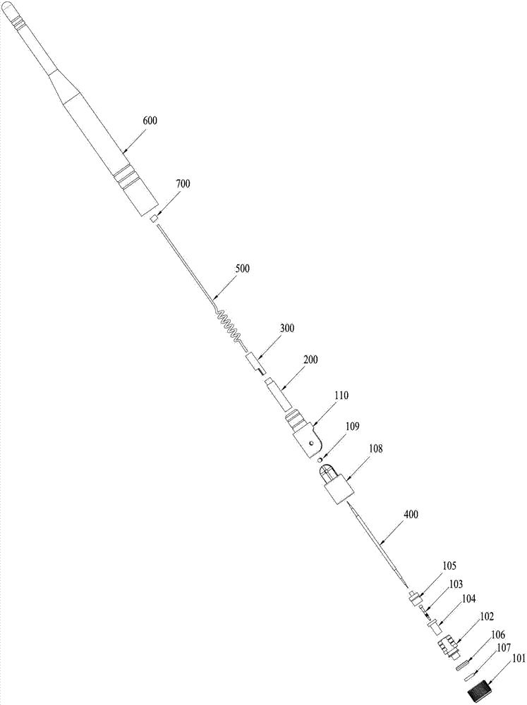
[0022] Please refer to Figures 1 to 5 , the dipole antenna of this embodiment includes a connector 100, a metal tube 200, a metal post 300, a wire 400, a coil 500, a sheath 600, and a metal tube 200 embedded in the connector 100, and the wire 400 Including signal wires and shielded wires, the shielded wires of the wires 400 pass through the metal tube 200 and are connected to the metal tube 200, and a stepped surface 302 is provided at the axial center of one end of the metal column 300, so The axial center of the stepped surface 302 is provided with a first through hole 301, and the signal line of the wire 400 is welded in the first through hole 301 by soldering. After the metal post 300 is processed into the stepped surface 302, It is more convenient to weld the signal line of the wire rod 400 to the first through hole 301 of the metal post 300. Since the wire rod is welde...


PUM


Abstract

The invention discloses a dipole antenna, which comprises a connector, a metal pole, a wire, a coil, a sheath and a metal tube which is embedded on the connector in a matching way. The wire comprises a signal wire and a shielding wire, wherein the shielding wire of the wire penetrates through the metal tube and is connected with the metal tube, the axial center of one end of the metal pole is provided with a stepping surface, the axial center of the stepping surface is provided with a first through hole, the signal wire of the wire is welded in the through hole, the axial center of the other end of the metal pole is provided with a second through hole, and the coil is riveted in the second through hole of the metal pole; and the coil, the metal pole, the metal tube and the wire are sleeved in the sheath, the sheath is fixedly connected with the connector, and a fixing plug is arranged between the coil and the sheath. The dipole antenna has the advantages that the frequency and signal of transmission are stable, and the product quality can be improved.

Description

technical field [0001] The invention relates to the technical field of wireless communication, in particular to a dipole antenna. Background technique [0002] In the technical field of wireless communication, a wireless communication device needs to send or receive signals through an antenna. For example: wireless routers, used to transmit signals of wireless communication devices. A dipole antenna in the prior art generally includes a connector, a copper pipe, a copper post, a wire, a coil, and a sheath. Wherein, the connector includes a signal end and a ground end; the signal end may be a pin or a hole. That is, the connector can be either male or female. The wire includes a signal wire and a ground wire. The signal wire is connected to the copper column and the signal end of the connector for signal transmission; the ground wire is connected to the copper tube and the ground end of the connector for shielding interference signals. The signal line of the coil and the ...

Claims


Application Information

Patent Timeline
Patent Type & Authority Applications(China)
IPC IPC(8): H01Q1/12H01Q1/36H01Q1/50H01Q9/16
Inventor 褚轩
Why Eureka
Try Eureka