Electric connecting device
An electrical connection device and technology of electrical connection, applied in the direction of conductive connection, electrical component connection, connection, etc., can solve the problems of time-consuming, labor-intensive, troublesome operation, etc., and achieve the effect of improving safety, compact structure, easy shielding and wrapping protective layer
- Summary
- Abstract
- Description
- Claims
- Application Information
AI Technical Summary
Problems solved by technology
Method used
Image

Examples
no. 1 example
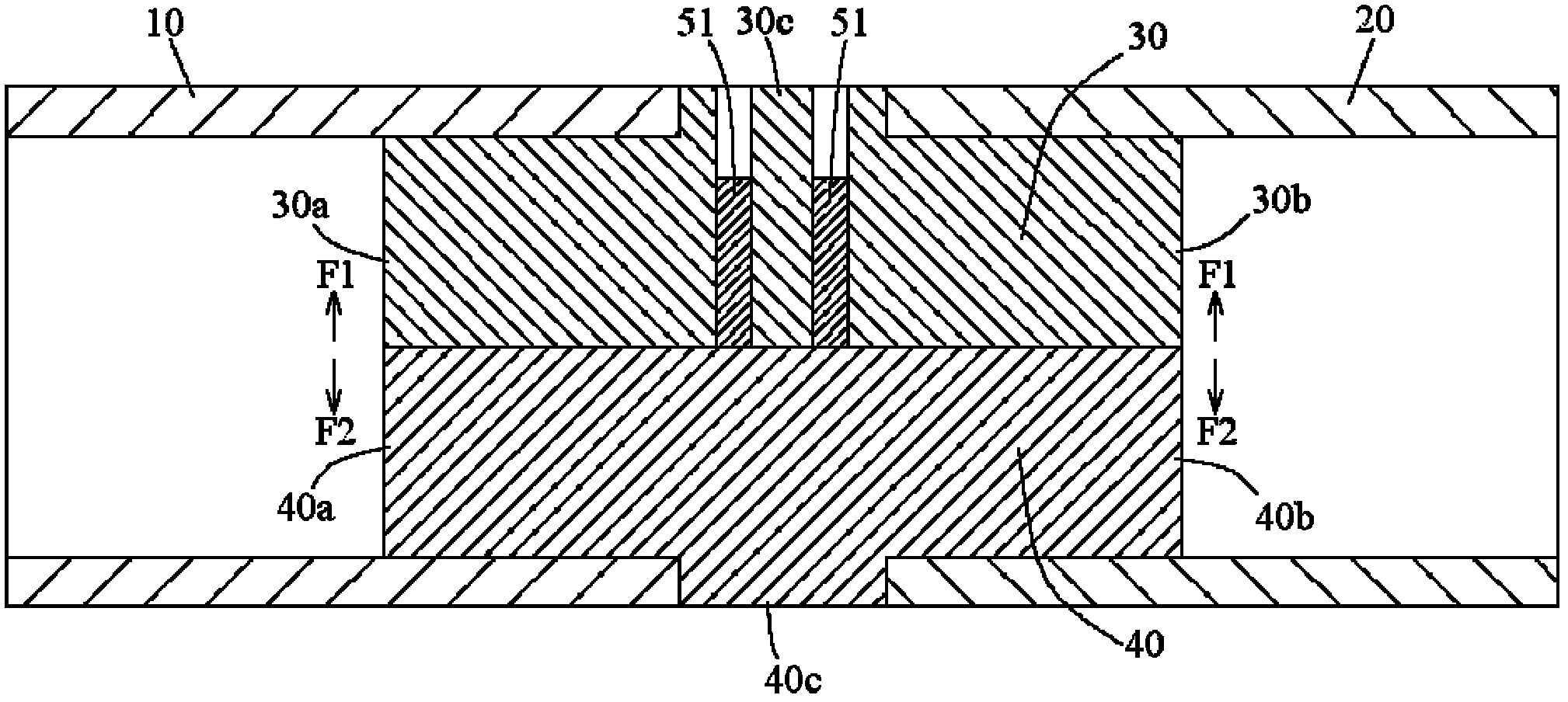
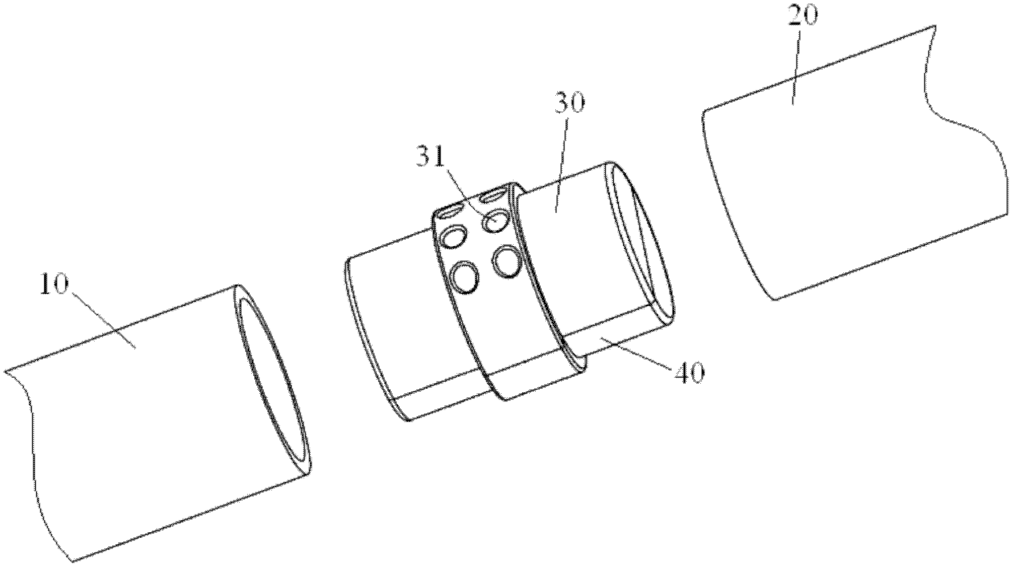
[0051] figure 1 A schematic cross-sectional view showing an electrical connection device according to a first exemplary embodiment of the present invention; figure 2a schematic perspective view showing an electrical connection device according to a first exemplary embodiment of the present invention; and image 3 An exploded schematic view of the electrical connection device according to the first exemplary embodiment of the present invention is shown.
[0052] exist Figure 1 to Figure 3 In the shown first embodiment, the electrical connecting device is used to electrically connect the first tubular busbar 10 and the second tubular busbar 20 to each other.
[0053] Such as image 3 As shown, the electrical connection device mainly includes a first conductive half body 30 and a second conductive half body 40 which are separated from each other. The first conductive half body 30 has two opposite first insertion ends 30a, 30b. In the present invention, in order to be able t...
no. 2 example
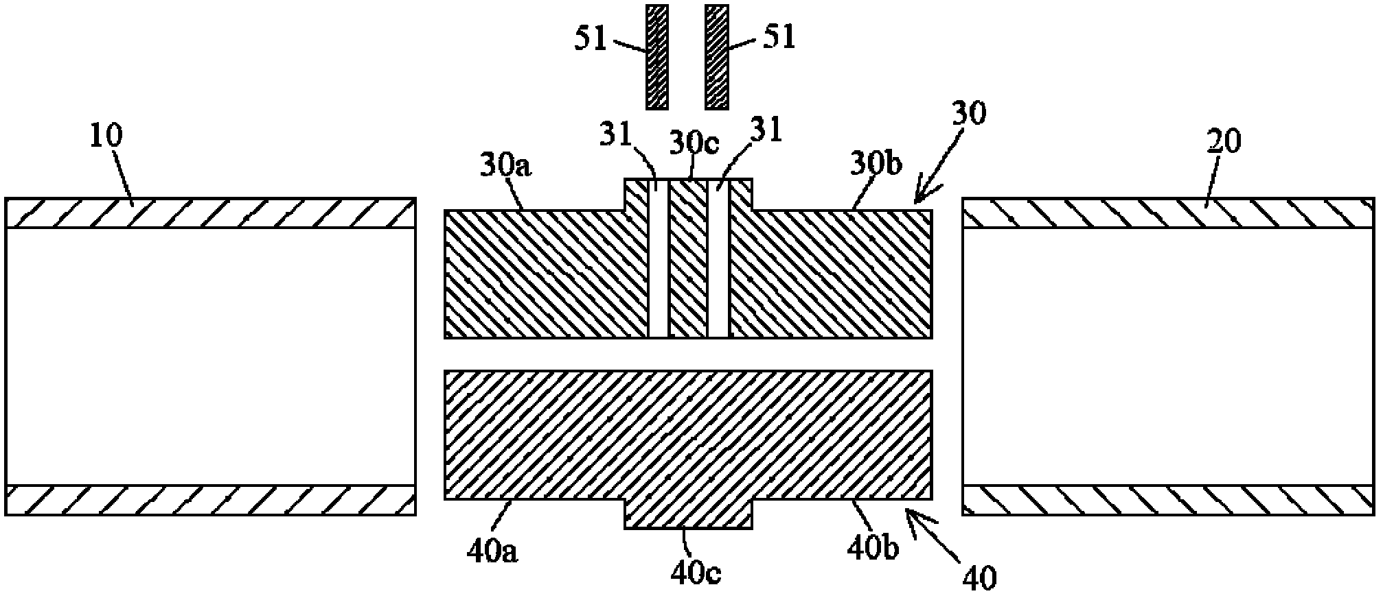
[0069] Figure 5 A schematic cross-sectional view of an electrical connection device according to a second exemplary embodiment of the present invention is shown.
[0070] and figure 1 Compared to the first embodiment shown, the Figure 5 The main difference of the second embodiment shown is: not only at least one first threaded through hole 31 is formed in the first raised portion 30c of the first conductive half body 30, but also at least one first threaded through hole 31 is formed in the second conductive half body 40 At least one second threaded through hole 41 is formed in the second protrusion portion 40c. Simultaneously, in the first threaded through hole 31 and the second threaded through hole 41, screw in the bolt 51 and the bolt 52 respectively, like this, the bolt 51 and the bolt 52 just can push the first conductor on the direction F1, F2 that separates from each other simultaneously. half body 30 and the second conductive half body 40 .
no. 3 example
[0072] Figure 6 A schematic perspective view of the first conductive semi-body of the electrical connection device according to the third exemplary embodiment of the present invention is shown.
[0073] and Figure 1-Figure 5 Compared with the first and second embodiments shown, the Figure 6 The main difference of the third embodiment shown is that: the first insertion end and the second insertion end of the first conductive half body 30 are no longer semicircular cylinders, but at least two concentric fan-shaped cylinders separated from each other .
[0074] Such as Figure 6 As shown, one insertion end of the first conductive semi-body 30 includes two concentric fan-shaped cylinders 30a1 and 30a2 spaced apart from each other. Similarly, the other insertion end of the first conductive half body 30 includes two concentric fan-shaped cylinders 30b1 and 30b2 spaced apart from each other. The advantage of adopting this structure is that the contact force and bonding force ...
PUM
 Abstract
Description
Claims
Application Information
 - R&D
- Intellectual Property
- Life Sciences
- Materials
- Tech Scout
- Unparalleled Data Quality
- Higher Quality Content
- 60% Fewer Hallucinations
Browse by: Latest US Patents, China's latest patents, Technical Efficacy Thesaurus, Application Domain, Technology Topic, Popular Technical Reports.
© 2025 PatSnap. All rights reserved.Legal|Privacy policy|Modern Slavery Act Transparency Statement|Sitemap|About US| Contact US: help@patsnap.com