Motor
A technology for motors and armatures, applied in the field of motors, can solve problems such as weakening of end cap strength
Active Publication Date: 2013-01-02
DENSO CORP
3 Cites 2 Cited by
AI-Extracted Technical Summary
Problems solved by technology
Therefore, there may be a problem that the strength of the end cap at this portion may be weakened due to the increase in th...
Method used
(2) In the state where the pair of power supply members 21, 22 are assembled on the end cover 3, the receiving recessed portion corresponding portions 21a, 22a are arranged to be aligned with the pair of inner side surfaces 3f in the width direction of the receiving recessed portion 3e flat. Connection grooves 21d, 21e, 22d, 22e for connecting terminals 31a, 32a of the first noise suppressing element 31 and the second noise suppressing element 32 are formed in the accommodation recess corresponding parts 21a, 22a. Therefore, the terminals 31a, 32a of the first noise suppression element 31 and the second noise suppression element 32 can be shortened, and the terminals 31a, 32a can be easily connected. That is to say, since the corresponding portions 21a, 22a for the receiving recesses are arranged outside the receiving recess 3e, the corresponding portions 21a, 22a for the receiving recesses will not narrow the corresponding portion 3e for the receiving recesses (the corresponding portions 21a, 22a for the receiving recesses do not occupy the receiving recess 3e). space inside). In this way, it is not necessary to stretch the terminals 31a, 32a of the first noise suppression element 31 and the second noise suppression element 32 accommodated in the accommodation recess 3e into the connection grooves 21d, 21e, 22d, 22e of the accommodation recess corresponding parts 21a, 22a. , the terminals 31 a and 32 a of the first noise suppression element 31 and the second noise suppression element 32 can be easily connected.
(4) The corresponding portions 21a and 22a of the receiving recesses are arranged at a position whose axial height is consistent with the axial height of the bearing 5, and are arranged at a position staggered axially from the...
Abstract
The invention provides a motor capable of easily ensuring strength of an end cover via shortening the width of a gap part. The motor is provided with: an armature; a yoke provided with a bottom and an open end and accommodating an armature; and an end cover. The end cover substantially closes the open end of the yoke. A connector portion, which bulges outward of the yoke, and a cutout portion are formed in the circumferential wall of the end cover. A pair of feed members is provided to extend from the interior of the end cover to the connector portion through the cutout portion. The end cover has an accommodation recess for accommodating the noise suppression element at a position corresponding to the cutout portion. Each feed member has an accommodation recess corresponding portion, which corresponds to the accommodation recess, and a cutout portion corresponding portion, which corresponds to the cutout portion. The distance between the accommodation recess corresponding portions of the feed members is greater than the distance between the cutout portion corresponding portions.
Application Domain
DC commutatorStructural association +1
Technology Topic
EngineeringNoise suppression +1
Image
Examples
- Experimental program(1)
Example Embodiment
[0014] Hereinafter, an embodiment embodying the present invention will be described with reference to the drawings.
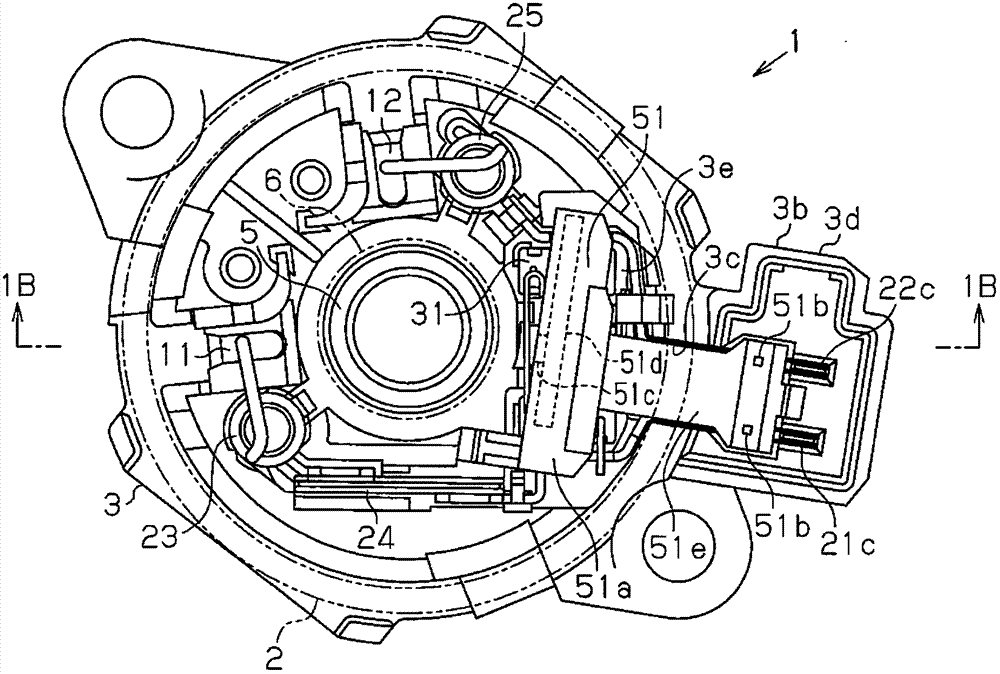
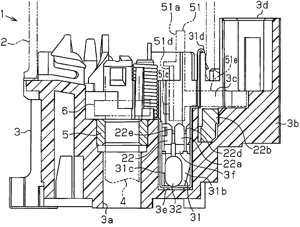
[0015] Such as Figure 1A as well as Figure 1B As shown, the motor 1 includes a yoke 2 formed of a magnetic metal material into a substantially cylindrical shape having a bottom and an open end, and an end cover 3 that is fixed to substantially close the open end of the yoke 2. A magnet (not shown) is fixedly mounted on the inner peripheral surface of the yoke 2. An armature is housed in the yoke 2. The rotating shaft 4 of the armature is rotatably supported by an unillustrated bearing and a bearing 5. The unillustrated bearing is held at the center of the bottom of the yoke 2, that is, the center of the end surface opposite to the open end. 5 is held on the bottom of the end cap 3. On the rotating shaft 4, in addition to a core wound with windings, a commutator and a sensor magnet 6 (refer to Figure 1B ). Such as Figure 1B As shown, the sensor magnet 6 of this embodiment is fixed to the rotating shaft 4 at a position shifted from the bearing 5 in the axial direction, that is, at a position near the bearing 5.
[0016] The end cover 3 is formed of a resin material, and is formed in a substantially cylindrical shape having a bottom and an open end corresponding to the open end of the yoke 2. A through hole 3 a that penetrates the bottom of the end cover 3 in the axial direction is formed in the center of the bottom of the end cover 3, and the through hole 3 a is used to insert the front end of the rotating shaft 4. The bearing 5 is held on the inner side of the yoke 2 of the through hole 3a. A connecting portion (not shown) on the load side is connected to the front end portion of the rotating shaft 4.
[0017] On a part of the peripheral wall of the end cover 3, a connector portion 3b that bulges to the outside of the yoke 2 when viewed from the axial direction of the rotating shaft 4, that is, the axial direction of the end cover 3 is integrally formed. A portion of the peripheral wall of the end cap 3 corresponding to the connector portion 3b is formed with a notch portion (interrupted portion of the peripheral wall) 3c that allows the inside of the end cap 3 to communicate with the connector portion 3b. The connector portion 3b has a cylindrical portion 3d extending in a substantially cylindrical shape along the axial direction so as to be able to fit an external connector of the control device (that is, a power supply device not shown). in Figure 1B Among them, the cylindrical portion 3d extends upward along the yoke 2.
[0018] Such as image 3 As shown, the end cap 3 has a receiving recess 3e at a position corresponding to the notch 3c. The width of the receiving recess 3e in the direction perpendicular to the radial direction (ie, the circumferential direction) is larger than the width of the notch 3c. The accommodating recess 3e is formed in a substantially quadrangular shape, which is composed of two sides extending in parallel along the radial direction when viewed from the axial direction, and a vertical direction along the radial direction to connect the two sides. Composed of two extended sides, the receiving recess 3e is along the axial direction (ie, image 3 In the depth direction of the paper surface) recessed.
[0019] Such as Figure 1A As shown, a pair of power supply brushes, that is, a first power supply brush 11 and a second power supply brush 12, are provided on the end cover 3. The pair of power supply brushes are arranged inside the yoke 2 when viewed from the axial direction. And is maintained to be able to move in the radial direction. The end cover 3 is provided with a torsion coil spring (not shown) that is urged radially inward in order to press the power supply brushes 11 and 12 into contact with the commutator. Such as figure 2 as well as image 3 As shown, the end cap 3 is provided with a pair of power supply members, namely a first power supply member 21 and a second power supply member 22. The pair of power supply members are electrically connected to the power supply brushes 11, 12, respectively, and from the shaft When viewed upward, it extends from the inside of the yoke 2 to the connector portion 3b (the cylindrical portion 3d) via the notch portion 3c.
[0020] In detail, such as Figure 4A as well as Figure 4B As shown, a pigtail 11a of the first power supply brush 11 is connected to the first power supply member 21 via a choke coil 23 and a plate-shaped thermistor (thermistor) 24. Such as Figure 4C as well as Figure 4D As shown, the pigtail wire 12a of the second power supply brush 12 is connected to the second power supply member 22 via the choke coil 25. Such as figure 2 as well as image 3 As shown, a pair of power supply members 21, 22 have receiving recess corresponding portions 21a, 22a corresponding to the receiving recess 3e and notch corresponding portions 21b, 22b corresponding to the notch 3c, and extend to the connector portion 3b The cylindrical part 3d. The front ends of the power supply members 21, 22 are provided with connection terminal portions 21c, 22c extending in the axial direction along the cylindrical portion 3d. Such as figure 2 as well as image 3 As shown, in a state where a pair of power supply components 21, 22 are assembled on the end cap 3, the interval between the corresponding portions 21a, 22a of the receiving recess is larger than the interval between the corresponding portions 21b, 22b of the notch . In addition, such as Figure 1B as well as image 3 As shown, in a state where the pair of power supply members 21, 22 are assembled on the end cap 3, the receiving recess corresponding portions 21a, 22a are flush with a pair of inner side surfaces 3f opposed in the width direction of the receiving recess 3e. Such as Figure 1B As shown, the axial ends of the corresponding portions 21a, 22a ( Figure 1B Middle and lower ends) and the opening peripheral edge of the receiving recess 3e of the end cap 3 ( Figure 1B The middle and upper ends) are arranged to abut in the axial direction. The corresponding portions 21a, 22a of the accommodating recesses and the bearing 5 at least partially coincide in the axial direction (refer to Figure 1B ).
[0021] The first noise suppression element 31 and the second noise suppression element 32 respectively include a pair of terminals 31a and 32a. Connection grooves 21d, 21e, 22d, 22e are formed in the corresponding portions 21a, 22a of the receiving recesses of the power supply members 21, 22, and these connection grooves serve as terminals for the first noise suppression element 31 and the second noise suppression element 32 31a, 32a connects the connection part. In detail, the corresponding portions 21a, 22a of the accommodating recesses have connecting grooves 21d, 21e, 22d, 22e for connecting the first noise suppression element 31 and the second noise suppression element 32 to the respective pair of terminals 31a, 32a. one of. The connection grooves 21d, 21e, 22d, and 22e are arranged in parallel on the respective power supply members 21 and 22 along the radial direction. The connecting grooves 21d, 21e, 22d, 22e of this embodiment have the terminals 31a, 32a of the first noise suppression element 31 and the second noise suppression element 32 that can be inserted into the connecting grooves 21d, 21e, 22d, 22e from the axial direction. shape.
[0022] The first noise suppression element 31 of this embodiment is formed by a pair of capacitors 31b combined. The pair of capacitors 31b are held on the holding member 31c so that their flat surfaces face each other. Each capacitor 31b has a first terminal and a second terminal. The first terminal is connected to the holding member 31c. The second terminal is led out to the opposite side of the opposing direction, and functions as a terminal 31 a for external connection of the first noise suppression element 31. A ground terminal 31d is formed on the holding member 31c, and in a state where the first noise suppression element 31 is assembled to the end cover 3, the ground terminal 31d is sandwiched between the end cover 3 and the yoke 2. The second noise suppression element 32 of the present embodiment is composed of a single resistor, and the main body of the second noise suppression element 32 excluding the terminal 32a can be arranged between the flat surfaces of the pair of capacitors 31b.
[0023] Each of the connecting grooves 21d, 21e, 22d, 22e has a predetermined width, and the predetermined width is set to correspond to the thickness of the terminals 31a, 32a of the corresponding noise suppression element 31, 32 (in the radial direction), and the terminal 31a, 32a can be pressed into the connecting grooves 21d, 21e, 22d, 22e. Each connection groove 21d, 21e, 22d, 22e is formed in each power supply member 21, 22 so as to extend in the axial direction, and is open to one end of the power supply member 21, 22 in the axial direction. The widths of the openings of the connection grooves 21d, 21e, 22d, and 22e are set so that the opening ends closer to the openings become larger. Such as Figure 1B as well as figure 2 As shown, the first noise suppression element 31 and the second noise suppression element 32 are accommodated in the accommodating recess 3e, and at this time the terminals 31a, 32a are pressed into the connection grooves 21d, 21e, 22d, 22e, thereby It is electrically connected to the connection grooves 21d, 21e, 22d, 22e and is held in the connection grooves 21d, 21e, 22d, 22e.
[0024] Such as Figure 5A as well as Figure 5B As shown, the connecting grooves 21d and 22d of the present embodiment have a shape in which the terminals 41a of the noise suppression element 41 of the motor of different specifications can be inserted (press-fitted). The noise suppression element 41 is formed of a single capacitor, and is installed on an inexpensive motor that does not have a resistor.
[0025] Such as Figure 1A as well as Figure 1B As shown, on the end cover 3 and at a position radially opposite to the sensor magnet 6 is assembled a rotation speed detecting component 51, which can detect the change in the magnetic force of the sensor magnet 6, that is, the rotating shaft 4 speed.
[0026] In detail, the rotation speed detecting member 51 includes a pair of sensor terminals 51b formed on a base member 51a formed of a resin material by insert molding, and a Hall IC 51c mounted on the substrate 51d. The substrate 51d is fixed to the base member 51a. The rotation speed detection part 51 is arranged in Figure 1B Shows a position shifted from the corresponding portion 22a (21a) of the receiving recess in the axial direction, and as Figure 1A As shown in the axial direction, the position of the receiving recess 3e (the first noise suppression element 31 and the second noise suppression element 32) is roughly covered. The above-mentioned Hall IC 51c (substrate 51d) is provided on the sensor magnet 6 side (axis center side) of the rotation speed detecting member 51.
[0027] The rotation speed detection member 51 has an extension part 51e which extends to the connector part 3b via the said notch part 3c. In a state where the rotation speed detecting member 51 is assembled to the end cap 3, the extended portion 51e is arranged at a position shifted in the axial direction from the notch corresponding portions 21b, 22b of the power supply members 21, 22, and Seen in the axial direction, the positions of the corresponding portions 21b and 22b of the covering notch are covered. The pair of sensor terminals 51b are buried in the extended portion 51e. The first end of each sensor terminal 51b is connected to the substrate 51d. The second end of each sensor terminal 51b protrudes in the axial direction (parallel) in the cylindrical portion 3d together with the connection terminal portions 21c, 22c of the power supply members 21, 22, and when an external connector is fitted into the cylindrical portion 3d, each The second end of the sensor terminal 51b is connected to the control device together with the connection terminal portions 21c and 22c.
[0028] Next, the function of the electric motor 1 configured as described above will be described.
[0029] When a drive current is supplied from an external control device to the windings of the armature via the power supply members (21, 22), the power supply brushes (11, 12), and the commutator, the armature is rotationally driven. When the sensor magnet 6 rotates together with the rotating shaft 4 of the armature, the change in the magnetic force of the sensor magnet 6 accompanying the rotation is detected by the rotation speed detecting part 51 (Hall IC51c), and a signal corresponding to the rotation speed of the rotating shaft 4 It is output to the control device. Various controls are performed based on this signal. When driving, noise is removed by the first noise suppression element 31 and the second noise suppression element 32 connected to the power supply members 21 and 22.
[0030] Next, the above-mentioned embodiment has the following advantages.
[0031] (1) A portion of the peripheral wall of the end cap 3 corresponding to the connector portion 3b is formed with a notch portion 3c that allows the inside of the end cap 3 to communicate with the connector portion 3b. Inside the end cap 3, a receiving recess 3e capable of accommodating the first noise suppression element 31 and the second noise suppression element 32 is formed at a position corresponding to the notch 3c. The width of the receiving recess 3e in the direction perpendicular to the radial direction (ie, the circumferential direction) is larger than the width of the notch 3c.
[0032] In the state where the pair of power supply members 21 and 22 are assembled on the end cap 3, the distance between the corresponding portions 21a and 22a of the receiving recesses corresponding to the receiving recess 3e is larger than that of the corresponding portions 21b and 22b corresponding to the notch 3c. The interval between is large. If implemented in this way, the width of the notch 3c (the interrupted portion of the peripheral wall) is reduced compared to the conventional motor in which the noise suppression element is arranged between the notch corresponding portions of a pair of power supply members corresponding to the notch. For example, the thickness of the end cap 3 can be made thin and the strength of the end cap 3 can be easily ensured.
[0033] (2) In a state where the pair of power supply members 21 and 22 are assembled on the end cap 3, the housing recess corresponding portions 21a, 22a are arranged to be flush with the pair of inner side surfaces 3f in the width direction of the housing recess 3e. Connection grooves 21d, 21e, 22d, 22e for connecting the terminals 31a, 32a of the first noise suppression element 31 and the second noise suppression element 32 are formed in the corresponding portions 21a, 22a of the receiving recesses. Therefore, the terminals 31a and 32a of the first noise suppression element 31 and the second noise suppression element 32 can be shortened, and the terminals 31a and 32a can be easily connected. In other words, since the accommodating recess corresponding portions 21a, 22a are arranged outside the accommodating recess 3e, the accommodating recess corresponding portions 21a, 22a do not narrow the accommodating recess 3e (the accommodating recess corresponding portions 21a, 22a do not occupy the accommodating recess 3e). Space within). In this way, there is no need to stretch the terminals 31a, 32a of the first noise suppression element 31 and the second noise suppression element 32 accommodated in the accommodation recess 3e into the connection grooves 21d, 21e, 22d, 22e of the accommodation recess corresponding parts 21a, 22a Therefore, the terminals 31 a and 32 a of the first noise suppression element 31 and the second noise suppression element 32 can be easily connected.
[0034] (3) A plurality of terminals 31a, 32a for connecting the first noise suppression element 31 and the second noise suppression element 32 are arranged in parallel along the radial direction on the corresponding portions 21a, 22a of the receiving recesses of the power supply members 21, 22 Connection grooves (21d, 21e, 22d, 22e) for connection. Therefore, the first noise suppression element 31 and the second noise suppression element 32 (a plurality of noise suppression elements) can be arranged between the pair of power supply members 21, 22, and the first noise suppression element 31 and the second noise suppression element 2 The terminals 31a and 32a of the noise suppression element 32 (a plurality of noise suppression elements) are connected. In the case where it is not necessary to stretch the respective terminals 31a and 32a of the first noise suppression element 31 and the second noise suppression element 32 long, the respective terminals can be shortened.
[0035] (4) The accommodating recess corresponding portions 21a, 22a are arranged at positions whose axial height matches the axial height of the bearing 5, and are arranged at positions shifted from the position of the rotation speed detecting member 51 in the axial direction. Therefore, there is no need to form the receiving recess corresponding portions 21a, 22a to avoid (circumvent) the rotation speed detecting member 51 when viewed in the axial direction, so that the power supply members 21, 22 can be shortened.
[0036] (5) The rotation speed detecting member 51 has an extension portion 51e extending to the connector portion 3b via the notch portion 3c, and the extension portion 51e is arranged at a position from the notch corresponding portions 21b, 22b of the power supply members 21, 22 Staggered along the axial position. Therefore, it is not necessary to form the notch corresponding portions 21b and 22b to avoid (circumvent) the extended portion 51e as viewed in the axial direction, and the width of the notch 3c (interrupted portion of the peripheral wall) can be further reduced. Therefore, not only can the thickness of, for example, the end cap 3 be reduced, but the strength of the end cap 3 can be more easily ensured.
[0037] The above-mentioned embodiment may be modified into the following forms.
[0038] · Although in the above-mentioned embodiment, the receiving recess corresponding portions 21a, 22a of the pair of power supply members 21, 22 are flush with the pair of inner side surfaces 3f in the width direction of the receiving recess 3e, it is not limited to this, and the receiving recess corresponds to The parts 21a and 22a may be arranged at positions shifted from the positions of the pair of inner side surfaces 3f when viewed in the axial direction.
[0039] · Although in the above-mentioned embodiment, a plurality of (two) connecting grooves 21d, 21e, 22d, 22e are provided in parallel in the radial direction on the respective receiving recess corresponding portions 21a, 22a, however, it is not limited to this. Only one connecting groove (connecting part) may be formed in each of the receiving recess corresponding parts 21a, 22a. In addition, in this case, only one noise suppression element can be installed. In addition, the motor may be configured to increase the number of connection grooves (connection portions) arranged on the motor, so that three or more noise suppression elements can be arranged.
[0040] · Although in the above embodiment, the accommodating recess corresponding portions 21a, 22a are arranged at positions whose axial height matches the axial height of the bearing 5, and are arranged in the axial direction from the position of the rotation speed detecting member 51 However, the shifted position is not limited to this, and the accommodating recess corresponding portions 21a and 22a may be arranged at positions that coincide with the rotation speed detecting member 51 in the axial direction.
[0041] -Although in the above-mentioned embodiment, the rotation speed detecting member 51 has an extension portion 51e extending to the connector portion 3b via the notch portion 3c, and the extension portion 51e is arranged in the notch corresponding portions 21b and 21b of the power supply members 21 and 22. The position of 22b is shifted in the axial direction, however, it is not limited to this, and the extended portion 51e may be arranged in a position that coincides with the notch corresponding portions 21b, 22b in the axial direction.
[0042] In the above-mentioned embodiment, the connecting portion is constituted by the connecting grooves 21d, 21e, 22d, 22e into which the terminals 31a, 32a of the first noise suppression element 31 and the second noise suppression element 32 can be inserted from the axial direction. However, as long as it is a connection part for connecting a terminal, it can also change to the connection part of another shape.
[0043] -In the above-mentioned embodiment, the width of each connection groove 21d, 21e, 22d, 22e is set so that each terminal 31a, 32a can be press-fitted into the corresponding connection groove 21d, 21e, 22d, 22e. However, it is not limited to this method. The width of the connecting groove may also be set so that each terminal 31a, 32a can only be pressed into a part of the connecting grooves. For example, the width of the connecting groove may also be set to increase the width of the connecting groove. However, the terminals 31a and 32a cannot be pressed into all the connection grooves. In addition, when it cannot be pressed in, brazing and other operations must be performed.
PUM


Description & Claims & Application Information
We can also present the details of the Description, Claims and Application information to help users get a comprehensive understanding of the technical details of the patent, such as background art, summary of invention, brief description of drawings, description of embodiments, and other original content. On the other hand, users can also determine the specific scope of protection of the technology through the list of claims; as well as understand the changes in the life cycle of the technology with the presentation of the patent timeline. Login to view more.