

12 pulse rectifier based on harmonic injection of DCM converter and control method thereof
A technology of pulse rectification and harmonic injection, applied in the direction of irreversible AC power input conversion to DC power output, output power conversion device, electrical components, etc., can solve the problems of complex circuit control, large loss, and inability to adapt to load changes, etc. , achieve the effect of reducing THD and simplifying the control loop
- Summary
- Abstract
- Description
- Claims
- Application Information
AI Technical Summary
Problems solved by technology
Method used
Image

Examples
Embodiment 1
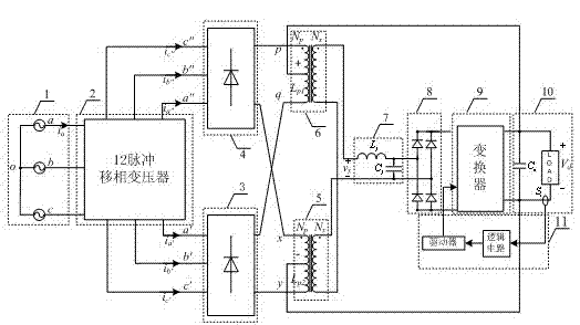
[0053] attached figure 1 Shown is a schematic structural diagram of a 12-pulse rectifier using a DCM mode AC-DC converter for harmonic injection, including a 12-pulse rectifier circuit and a DCM mode AC-DC converter. Among them, the 12-pulse rectification circuit includes a three-phase voltage source 1; a phase-shifting transformer 2; a three-phase rectification bridge 3, 4; harmonic injection balance reactors 5, 6 and an output circuit 10. The AC-DC converter in DCM mode includes a harmonic injection circuit including an LC filter circuit 7 , a single-phase rectifier bridge 8 , a power converter 9 and a control loop 11 . Harmonic injection balance reactors 5 and 6 each add a winding, connect the opposite ends of the two additional windings, and the two ends of the same name are used as the input of the AC-DC converter working in DCM mode; the AC-DC converter in DCM mode The output of the 12-pulse rectifier circuit is connected to the output filter capacitor. Among them, th...
Embodiment 2
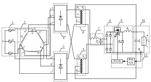
[0055] by Figure 20 The P-type 12-pulse autotransformer rectifier based on the DCM mode flyback converter for harmonic injection is taken as an example, and its working principle is described. and are the turns of the long and short windings, respectively. The waveform of the input current as Figure 26 As shown by the dotted line in the middle, multiple square waves are superimposed to form a ladder wave. The dotted lines in (a)-(g) are the phase current waveforms of the P-type 12-pulse autotransformer output phases a', a", b', c', and c", respectively. a The expression for the phase input current is , ( f ) The dotted line is the input current of phase a, and its THD is relatively large. The principle of harmonic injection in the present invention is to inject harmonics so that the current at the output side of the phase-shifting transformer is formed as Figure 26 The triangular waveform shown in the solid line (a)-(g) is converted to the AC side to form a sinuso...
Embodiment 3
[0062] attached Figure 29 middle i Lp It is the primary side current of the flyback converter, and its waveform tracks the change of the input voltage very well. After L f 、C f After filtering i x In order to balance the current waveform in the secondary winding of the reactor, the triangular harmonic current needs to be injected. attached Figure 30 middle It is the output of the phase-shifting transformer after harmonic injection phase current waveforms, with the attached Figure 26 The waveforms in the theoretical analysis are similar. attached Figure 31 This is the three-phase input current waveform after harmonic injection of the P-type 12-pulse autotransformer rectifier through the DCM mode flyback converter. At this time, the input current THD is about 8.9%, which meets the requirements of relevant aviation standards. Figure 2-19 , Figure 21-25 12-pulse rectifiers such as other types of harmonic injection, its working principle is the same as Figure ...
PUM
 Abstract
Description
Claims
Application Information