Uplink measurement reference signal sending control method and user equipment

A technology for measuring reference signals and user equipment, which is applied in the field of SRS transmission control methods and user equipment, and can solve problems such as UE transmission power exceeding the maximum transmission power

Inactive Publication Date: 2013-01-02
ZTE CORP
View PDF1 Cites 16 Cited by
  • Summary
  • Abstract
  • Description
  • Claims
  • Application Information

AI Technical Summary

Problems solved by technology

[0009] When SRS and PUSCH or SRS and non-truncated PUCCH or SRS and PUSCH and PUCCH are sent simultaneously

Method used


Image

  • Uplink measurement reference signal sending control method and user equipment
  • Uplink measurement reference signal sending control method and user equipment

Examples


Embodiment 1

[0097] In this embodiment, it is assumed that the UE is configured with 4 uplink CCs, which are CC1, CC2, CC3, and CC4. A PA scene.

Embodiment 1-1

[0099] Assume that there is PUSCH transmission in CC1, SRS transmission in CC2, SRS transmission in CC3, and no transmission in CC4 in the current subframe.

[0100] It is assumed that the UE finally transmits the PUSCH on CC1 and the SRS on CC3.

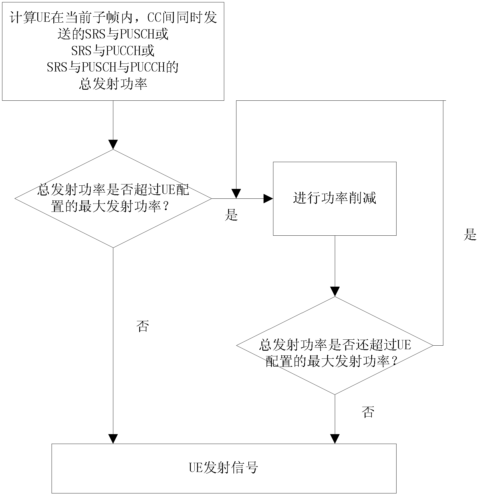
[0101] Then the UE judges whether the sum of the transmit power of the PUSCH on CC1 and the SRS on CC3 exceeds the maximum transmit power P configured by the UE. CMax , if the sum of transmit power exceeds P CMax ,which is:

[0102] P CC1PUSCH (i)+P CC3SRS (i)>P CMax

[0103] Then perform power reduction. Here, power reduction method 1 is used, that is, proportional reduction. The transmit power of PUSCH on CC1 and SRS on CC3 is multiplied by a unified power control factor W(i), and by controlling the power control factor W( The value of i) reduces the transmit power of PUSCH on CC1 and SRS on CC3 in proportion until the sum of transmit power does not exceed P CMax up to, that is:

[0104] W(i)·(P CC1PUSCH (i)+P CC3SRS (i)...

Embodiment 1-2

[0107] Assume that CC1 sends PUCCH, CC2 sends PUSCH, CC3 sends SRS, and CC4 sends SRS.

[0108] It is assumed that the UE finally transmits the PUCCH on CC1, the PUSCH on CC2, the SRS on CC3, and the SRS on CC4.

[0109] Then the UE judges whether the sum of the transmit power of PUCCH on CC1, PUSCH on CC2, SRS on CC3, and SRS on CC4 exceeds the maximum transmit power P configured by the UE. CMax , if the sum of transmit power exceeds P CMax ,which is:

[0110] P CC1PUCCH (i)+P CC2PUSCH (i)+P CC3SRS (i)+P CC4SRS (i)>P CMax

[0111] Power reduction is performed here. Power reduction method 2 is used here, that is, reduction is performed according to the mixed priority based on physical channels and SRS. Assume that priority definition method 1 is used at this time, that is, PUCCH has the highest priority, followed by SRS, and PUSCH has priority lowest level. Then reduce the transmit power of PUSCH so that the sum of transmit power does not exceed P CMax ,which is:

...


PUM


Abstract

The invention provides an uplink measurement reference signal sending control method, comprising the steps that if user equipment is in a current sub-frame, a sounding reference signal (SRS) and a physical uplink shared channel (PUSCH) exists between uplink component carriers; or a physical uplink control channel (PUCCH) of the SRS and a non-truncation structure exists; or the SRS, the PUSCH and the PUCCH are sent at the same time, namely the sum of emission power of each physical channel and the SRS sent by the current sub-frame is calculated by the user equipment; and if the sum of the emission powers is more than the maximum emission power configured by the user equipment, power reduction is carried out. The invention further provides the user equipment. According to the uplink measurement reference signal sending control method, the reliability of the SRS sent by the PUSCH and/or the PUCCH is improved.

Description

technical field [0001] The present invention relates to the field of digital communication, in particular to LTE (Long Term Evolution, 3GPP long-term evolution) and LTE-Advanced (Long Term Evolution Advanced, advanced 3GPP long-term evolution), in particular, to a kind of SRS (Sounding reference signal, measurement reference signal) to send a control method and user equipment. Background technique [0002] The LTE-Advanced system is an evolved version of the LTE system. Its purpose is to meet the higher demands and more applications of the wireless communication market in the next few years, and to meet and exceed the requirements of IMT-Advanced (International Mobile Telecommunications-Advanced, Advanced International Mobile Communications). requirements while maintaining good backward compatibility with LTE. [0003] In order to meet this requirement, LTE-Advanced adopts CA (Carriers Aggregation, carrier aggregation) technology to further support wider communication bandw...

Claims


Application Information

Patent Timeline
IPC IPC(8): H04W52/30
Inventor 林志嵘夏树强戴博任璐
Owner ZTE CORP
Why Eureka
Try Eureka