
Patsnap Eureka
For R&D, Patsnap Eureka makes reading and utilizing patents & technical documents easy.
Patsnap Eureka AIR
Designed for self-driven R&D workflows. Generate viable solutions, solve complex R&D challenges, empower your innovation with AI.

Patsnap Eureka Materials
Designed for material experts only. Revolutionize your material R&D, from search, analyze, to developing new materials.

TechResearch
Generate reliable direction feasibility study reports for your R&D in just a few steps.

TechSeek
Discover and master advanced knowledge NOW. Basics, ideas, possibilities, all at once.

TechMind
As an expert in R&D Theories, TechMind can generates customized viable solutions instantly.

TechRisk
Analyze your overall solution with one click, know your potential R&D risks in advance.

TechMonitor
Get weekly tech updates, stay abreast of the latest tech innovations and key insights.
Universal direct-current LED driving power source
A technology of LED driving and power supply, applied in the direction of electric light source, light source, electric lamp circuit layout, etc., can solve the problems of limited application scope, trouble and difficulty, and lack of integrated circuits, and achieve the effect of expanding the application scope
- Summary
- Abstract
- Description
- Claims
- Application Information
AI Technical Summary
Problems solved by technology
Method used
Image

Examples
Embodiment 1
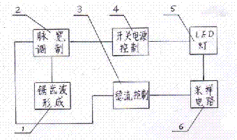
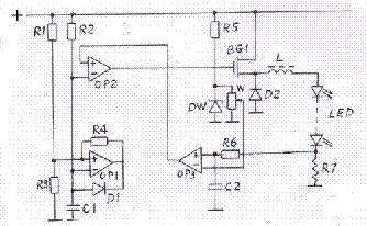
[0022] Example 1: Combining figure 2 , for the following description, figure 1 The sawtooth wave in module 1 is formed by figure 2 The operational amplifier OP1 in the circuit is composed of resistors R1, R2, R3, R4, diode D1 and capacitor C1. One end of the resistor R1 is connected to the positive pole of the power supply, and the other end is connected to each end of the resistors R3 and R4, and then connected to the positive input pole of the operational amplifier OP1. The resistor R4 The other end is connected to the negative pole of diode D1 and then connected to the output terminal of op amp OP1, the other end of resistor R3 is connected to the common terminal, one end of resistor R2 is connected to the positive pole of the power supply, the other end is connected to the end of capacitor C1 and the positive pole of diode D1, and then connected to the negative pole of op amp OP1 input terminal. The other end of the capacitor C1 is connected to the common end. In this ...
Embodiment 2
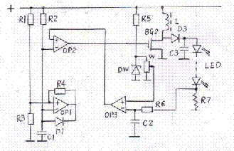
[0023] Example 2: Combining image 3 , for the following description, figure 2 The steady flow control module 3 in the image 3 The connection is changed to: the other end of the resistor R6 is connected to one end of the capacitor C2, and then connected to the negative pole of the input terminal of the operational amplifier OP3, and the sliding contact of the trimmer potentiometer W is connected to the positive pole of the input terminal of the operational amplifier OP3. figure 2 The switching power supply in the control 4 in the image 3 In the middle, it is changed to: it is composed of VMOS tube BG2, diode D3, capacitor C3 and inductor L. The output terminal of the operational amplifier OP2 is connected to the input of the switching power supply control module 4, that is, the gate of the VMOS transistor BG2, the source of the VMOS transistor BG2 is connected to the common terminal, the drain of the VMOS transistor BG2 is connected to the positive pole of the diode D3, ...
Embodiment 3
[0024] Example 3: Binding Figure 4 , for the following description, Figure 4 The switching power supply control module 4 in the image 3A semiconductor device DW, a resistor R8 and a diode D4 with voltage stabilizing properties are added. The negative pole of the diode D3 is connected to the negative pole of the semiconductor device DW with voltage stabilizing characteristics, the positive pole of the semiconductor device DW with voltage stabilizing characteristics is connected to one end of the resistor R8 and then connected to the positive pole of the diode D4, the negative pole of D4 is connected to the negative pole of the input terminal of the operational amplifier OP3, and the other end of the resistor R8 Connect to the common terminal. This is a no-load overvoltage protection circuit for a boost switching circuit. When the load LED light is open or the output voltage rises too high due to other reasons, the semiconductor device DW with voltage stabilization characte...
PUM
 Abstract
Description
Claims
Application Information
 - R&D Engineer
- R&D Manager
- IP Professional
- Industry Leading Data Capabilities
- Powerful AI technology
- Patent DNA Extraction
Browse by: Latest US Patents, China's latest patents, Technical Efficacy Thesaurus, Application Domain, Technology Topic, Popular Technical Reports.
© 2024 PatSnap. All rights reserved.Legal|Privacy policy|Modern Slavery Act Transparency Statement|Sitemap|About US| Contact US: help@patsnap.com