Power generating apparatus of renewable energy type

一种发电装置、再生能型的技术,应用在风能发电、风力发电机组件、安装/支撑风力发动机的配置等方向,能够解决发电机热损失变大等问题

Inactive Publication Date: 2013-01-02
MITSUBISHI HEAVY IND LTD
View PDF6 Cites 13 Cited by
  • Summary
  • Abstract
  • Description
  • Claims
  • Application Information

AI Technical Summary

Problems solved by technology

[0003] However, when the size of the regenerative power generation device increases and the output of the generator increases, the heat loss from the generator also increases.

Method used


Image

  • Power generating apparatus of renewable energy type
  • Power generating apparatus of renewable energy type
  • Power generating apparatus of renewable energy type

Examples


no. 1 example

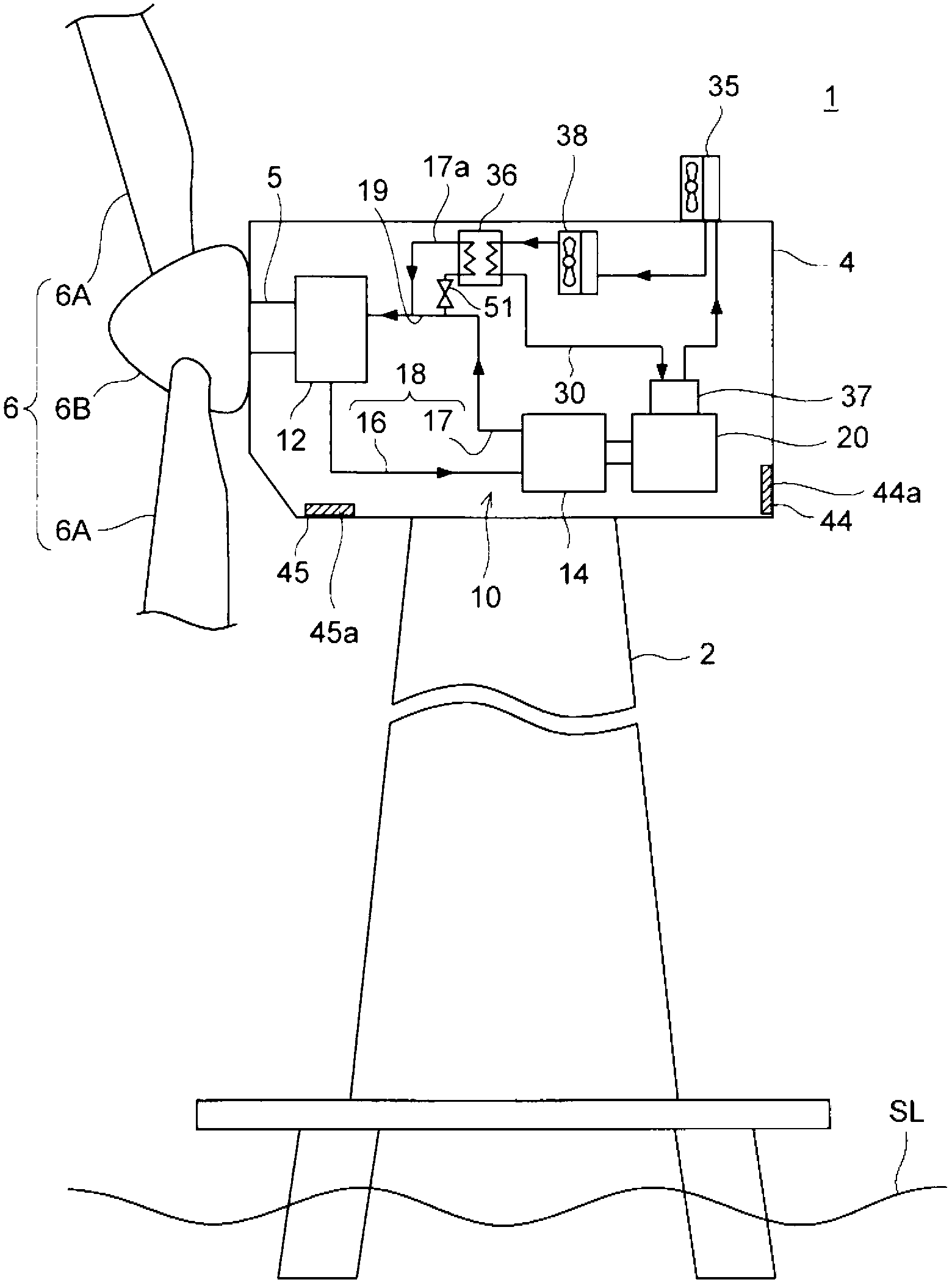
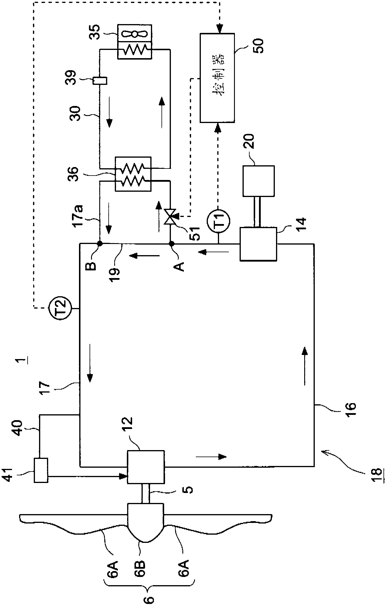
[0058] Reference figure 1 with figure 2 The wind power generation device according to the first embodiment of the present invention will be described. here, figure 1 Is a diagram showing the overall structure of the wind power generation device of the first embodiment, figure 2 It is a diagram showing an example of the structure of the oil pipeline and the cooling medium pipeline.

[0059] Such as figure 1 As shown, the wind power generator 1 mainly includes a tower 2, a nacelle 4 supported by the tower 2, and a rotating body 6 that rotates using energy of wind.

[0060] figure 1 Here, the offshore wind power generator installed on the sea surface SL is exemplified as the wind power generator 1, but the wind power generator 1 may be installed on land.

[0061] The rotating body 6 includes at least one (for example, three) blades 6A and a hub 6B that supports the blades 6A. The hub 6B is connected to the main shaft 5 housed in the nacelle 4. Therefore, when the blade 6A receives w...

no. 2 example )

[0103] Next, the wind power generator of the second embodiment will be described. The wind power generator of this embodiment has the same structure as the wind power generator 1 of the first embodiment already described, except for the cooling mechanism in the transformer chamber 72. Therefore, the components common to the first embodiment are given the same reference numerals, and their description is omitted, and the description will focus on the parts different from the first embodiment.

[0104] Such as Figure 7 As shown, the wind power generator 1 includes a transformer room cooler 91 that cools the transformer room 72. The transformer compartment cooler 91 is connected to a cooling medium line 30 that supplies a cooling medium to the oil cooler 36. In the same figure, the cooling medium line 30 on the side of the oil cooler 36 and the cooling medium line 30' on the side of the transformer chamber 72 are connected to the heat exchanger 35 for heat exchange between the env...


PUM


Abstract

A power generating apparatus includes a rotating shaft, a hydraulic pump driven by the rotating shaft, a hydraulic motor driven by operating oil supplied from the hydraulic pump; and a generator coupled to the hydraulic motor. The apparatus further includes an oil line connected to the hydraulic pump and the hydraulic motor for circulating the operating oil between the hydraulic pump and the hydraulic motor, an oil cooler connected to the oil line for cooling the operating oil by heat exchange with a cooling medium, a cooling-medium line supplying the cooling medium to the oil cooler; a bypass line diverging from at least one of the oil line and the cooling-medium line and merging into at least one of the oil line and the cooling-medium line to bypass the oil cooler; and a flow regulating valve in at least one of the oil line and the cooling-medium line.

Description

Technical field [0001] The present invention relates to a regenerative power generation device that transmits the rotational energy of a rotating body obtained from a regenerative energy to a generator via a hydraulic transmission device, and more particularly relates to a regenerative power generation device with a cooling function of the hydraulic transmission device. Background technique [0002] In recent years, from the viewpoint of protecting the global environment, regenerative power generation devices such as wind power generation devices that use wind power and tidal current power generation devices that use tidal current, river, or ocean current energy have been spreading. These regenerative power generation devices are advancing in size in order to improve power generation efficiency. In particular, wind power generators installed on the sea often have a higher construction cost than wind power generators installed on land. Therefore, it is required to increase the pow...

Claims


Application Information

Patent Timeline
Patent Type & Authority Applications(China)
IPC IPC(8): F03D9/00F03D11/00
CPCY02E10/721F05B2260/20F03D9/001F05B2260/406F03D9/25F03D9/28F03D13/25F03D15/20F03D80/60Y02E10/72Y02E10/727Y02P80/10F03D80/70
Inventor 明石悠松尾毅佐藤慎辅龟田拓郎
Owner MITSUBISHI HEAVY IND LTD
Why Eureka
Try Eureka