Light-emitting diode lamp

A light-emitting diode lamp and light-emitting diode technology, which is applied to light sources, semiconductor devices of light-emitting elements, point light sources, etc., can solve problems such as low heat transfer efficiency of light-emitting diodes, and achieve the effect of reliable thermal contact

Inactive Publication Date: 2013-01-02
奥斯曼根纳德维奇库耶夫
View PDF3 Cites 54 Cited by
  • Summary
  • Abstract
  • Description
  • Claims
  • Application Information

AI Technical Summary

Problems solved by technology

[0012] - Low heat transfer efficiency from LEDs via PCB to case / heat sink;

Method used


Image

  • Light-emitting diode lamp
  • Light-emitting diode lamp
  • Light-emitting diode lamp

Examples


Embodiment Construction

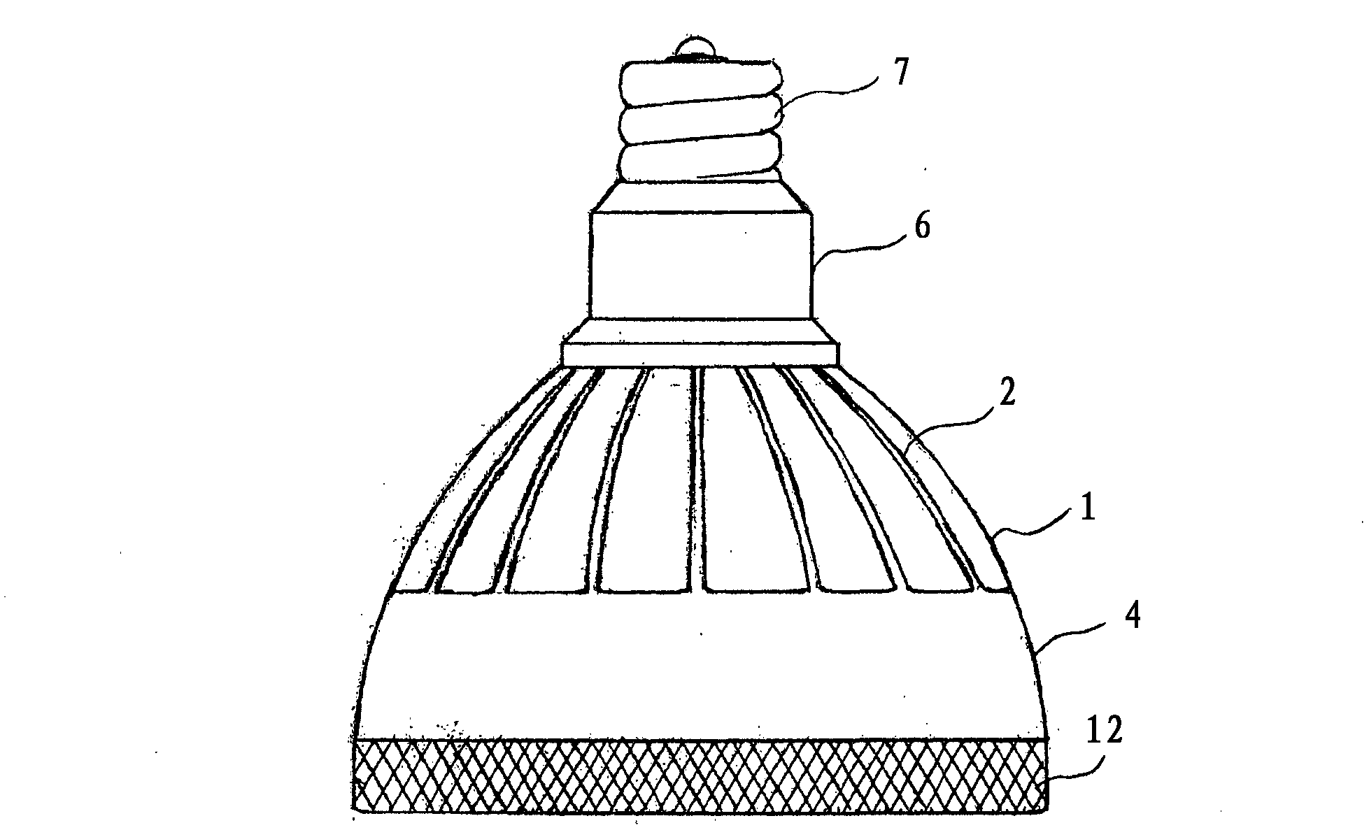
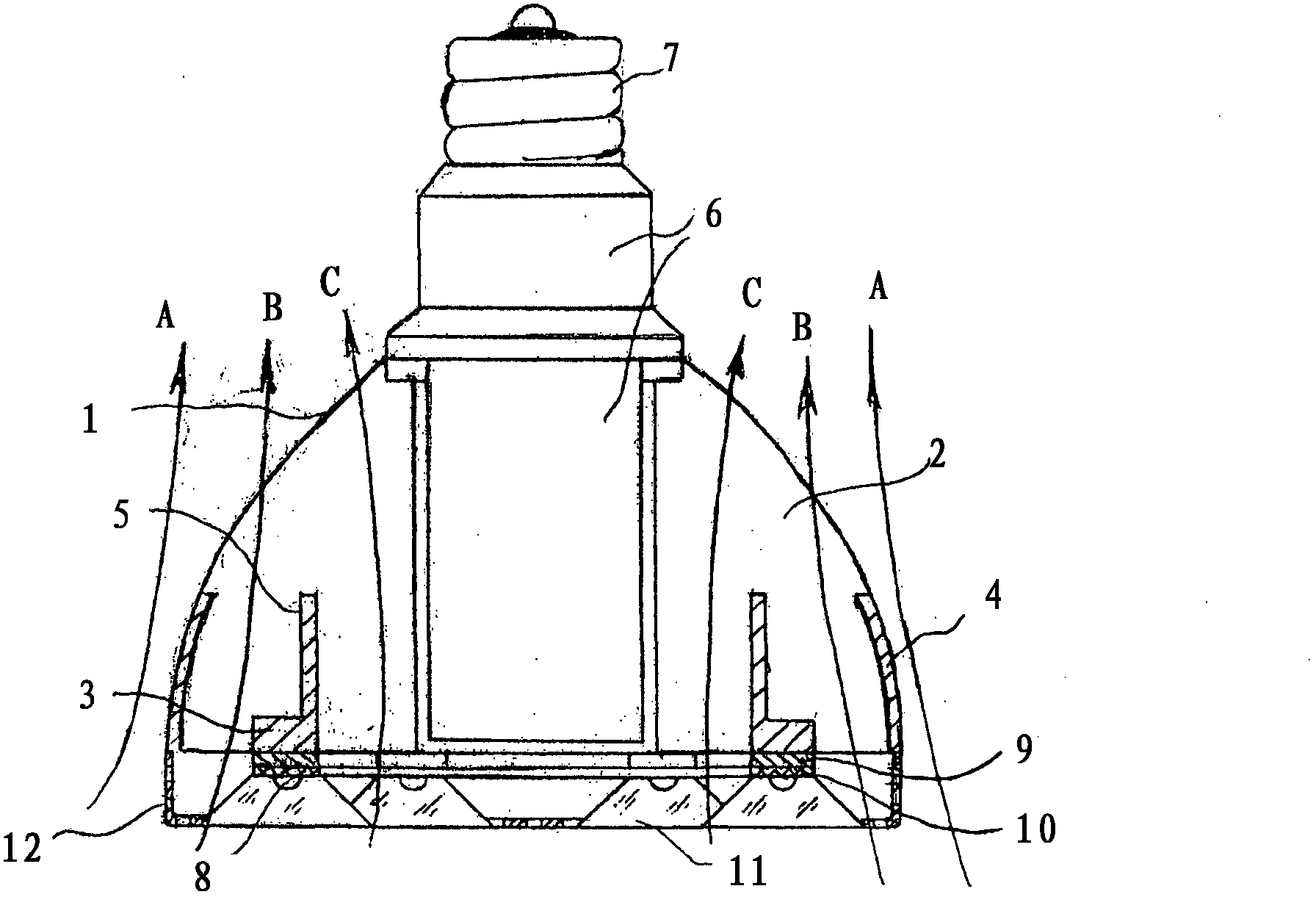
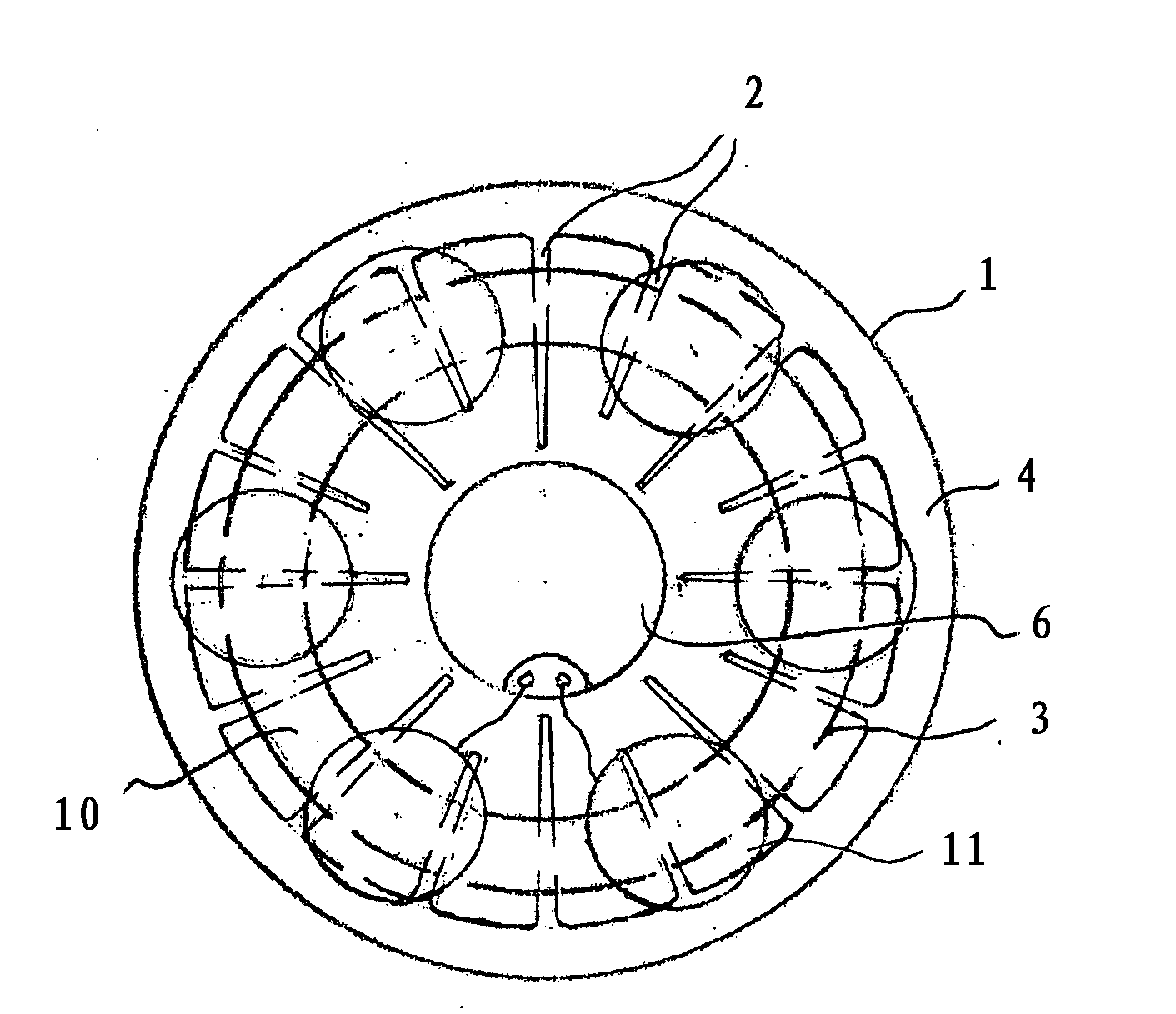
[0037] refer to figure 1 , a LED lamp is schematically drawn on the figure, and it includes: a rotating hollow radiator 1, a radial-longitudinal vane 2 on the outer periphery of the radiator, an annular spacer 3 connected to the end of the vane 2; and The end of the blade 2 is adjacent to the outer wall 4 on the side of the spacer 3; the inner wall 5 connected to the annular spacer 3 and straddling the blade 2; the power supply 6 in the central part of the radiator 1; the screw base 7; light-emitting diodes 8; copper plate 9; printed circuit board 10 and diffuser 11.

[0038] The lamp can be equipped with a cover 12 placed on the heat sink 1 on the side of the LED 8 and perforated at both ends and sides of the cover 12 for the purpose of free passage of convective heat flow. The cover 12 is the part that prevents any contact with the current carrying unit of the LED lamp and prevents physical destruction of the LED modules of the lamp. In addition, the cover adds to the over...


PUM


Abstract

The light-emitting diode lamp comprises: a radiator having a hollow central part and longitudinal radial ribs that form the outer counter of the lamp; and light-emitting diodes mounted on an annular platform at the foot of the radiator so as to be capable of contact heat transfer to the radiator. The ends of the longitudinal radial ribs are connected to the annular platform.

Description

technical field [0001] The present invention relates to lighting devices, in particular to LED lamps (light sources, luminous objects) intended for industrial, public, office and living rooms and spaces. Background technique [0002] Compared with commonly used electric light sources (incandescent lamps, fluorescent lamps, gas discharge halogen, sodium, mercury, etc. lamps), light-emitting diode groups have the highest level of luminous efficiency (up to 150 lumens / watt) of the featured light source. [0003] LED lamps based on high-power light-emitting diodes are high-energy-efficiency, environmentally friendly, and long-life light sources. [0004] The main indicator of the efficiency of a lighting lamp is its luminous efficacy measured in [lm / W], ie, the luminous flux in lumens per unit of electrical power consumed (in W). [0005] A standard LED lamp utilizing light emitting diodes, also includes some dependent optics (reflector, optical lens), heat sink and power supp...

Claims


Application Information

Patent Timeline
Patent Type & Authority Applications(China)
IPC IPC(8): F21K99/00F21Y101/02
CPCF21K9/137F21V29/2262F21V29/246F21V29/2293F21V29/20F21Y2101/02F21K9/00F21V29/2206F21V29/2231F21V29/75F21V29/773F21V29/83F21V29/89F21K9/23F21K9/233F21Y2115/10F21V29/74
Inventor K·L·佩特罗斯安
Owner 奥斯曼根纳德维奇库耶夫
Why Eureka
Try Eureka