Chain riveting method utilizing oil pressure

A chain and riveting head technology is applied in the field of chain riveting head using hydraulic pressure, which can solve the problems of increasing the specification, unable to realize the jumping joint riveting head, and the chain riveting head cannot meet people's environmental concerns, so as to avoid leakage of riveting. Effect

A chain and riveting head technology is applied in the field of chain riveting head using hydraulic pressure, which can solve the problems of increasing the specification, unable to realize the jumping joint riveting head, and the chain riveting head cannot meet people's environmental concerns, so as to avoid leakage of riveting. Effect

CN102861864AActive Publication Date: 2013-01-09SUZHOU CHUNMENG INTELLIGENT TECHNOLOGY CO LTD

Image

  • Chain riveting method utilizing oil pressure
  • Chain riveting method utilizing oil pressure
  • Chain riveting method utilizing oil pressure

Examples


Embodiment Construction

[0046] In order to make the object, technical solution and advantages of the present invention clearer, the present invention will be further described in detail below in conjunction with the accompanying drawings and embodiments. It should be understood that the specific embodiments described here are only used to explain the present invention, not to limit the present invention.

[0047] A method for chain riveting by hydraulic pressure, comprising the following steps:

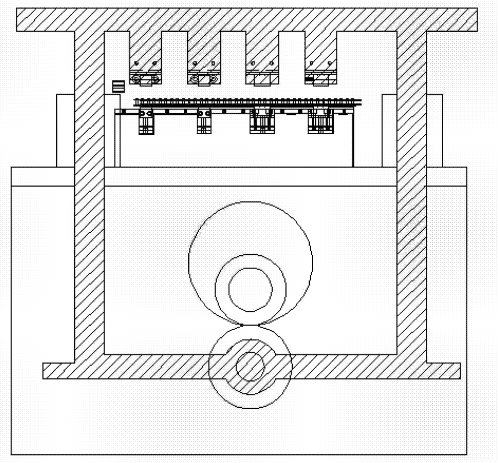
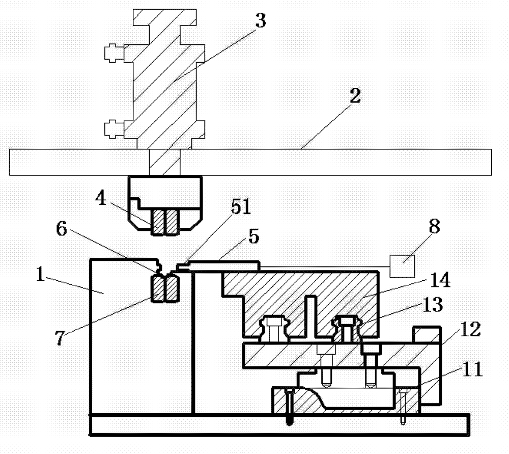
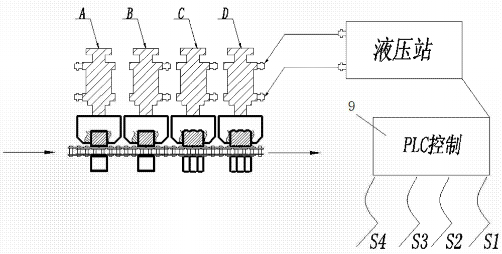
[0048] Step 1 provides a hydraulic chain riveting head machine, including a workbench and a support frame, a hydraulic cylinder is arranged on the support frame, and an upper riveting die is connected below the hydraulic cylinder; a chain channel is arranged on the workbench , the position corresponding to the upper rivet die in the chain channel is provided with a lower rivet die; the workbench is also provided with a moving plate, and the side of the moving plate close to the chain channel is a sawtooth st...


PUM


Abstract

A chain riveting method utilizing oil pressure includes step 1, placing a chain with pins into a chain passage, aligning a first chain link required to be riveted to a riveting die; step 2, starting a hydraulic cylinder and a moving plate driving device by a control device, and enabling the hydraulic cylinder to drive the riveting die to realize primary riveting; step 3, driving a moving plate to drive the chain to move by the moving plate driving device after finishing the primary riveting; and step 4, repeating the step 2 and the step 3 to complete riveting of the whole chain. By combination of a PLC control device and an oil pressure system, full-automatic, intelligent and multifunctional riveting can be realized, four-side riveting and two-side riveting can be realized, and by the chain riveting method, one link of the whole chain can be free of riveting while the other links are riveted, so that the chain can be cut off conveniently for subsequent detection.

Description

technical field [0001] The invention relates to the chain manufacturing industry, in particular to a method for riveting a chain head by using oil pressure. Background technique [0002] In the chain manufacturing industry, the assembled chain must be riveted. However, because the current chain riveting equipment adopts the principle of mechanical linkage, the design of the riveting machine is complex in structure and bulky, and the strength and speed of mechanical stamping riveting are completely unacceptable. control, the quality of the riveting head cannot be adjusted to the best state, and all the chain links are riveted, and the function of skipping the joint cannot be realized, resulting in a lot of waste. In addition, the noise of mechanical stamping is large, which can no longer meet the requirements of construction of energy-saving and environmental protection. According to the requirements of the society, the equipment transformation of the chain manufacturing indu...

Claims


Application Information

Patent Timeline
09 Jan 2013
Publication
CN102861864A
IPC
B21L9/06
Inventors
何汉朝; 何治富