Tension spring

A tension spring and spring chamber technology, applied in the field of tension springs, can solve the problems of long structure length and large installation space, and achieve the effect of uniform distribution

Inactive Publication Date: 2013-01-09
STABILUS
View PDF6 Cites 13 Cited by
  • Summary
  • Abstract
  • Description
  • Claims
  • Application Information

AI Technical Summary

Problems solved by technology

[0003] Such tension springs have the disadvantage that they require a large installation space due to their long construction length

Method used


Image

  • Tension spring
  • Tension spring

Examples


Embodiment Construction

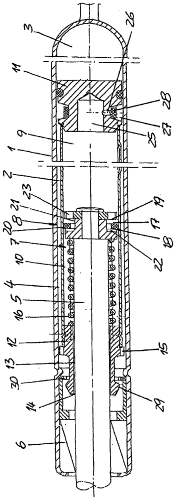
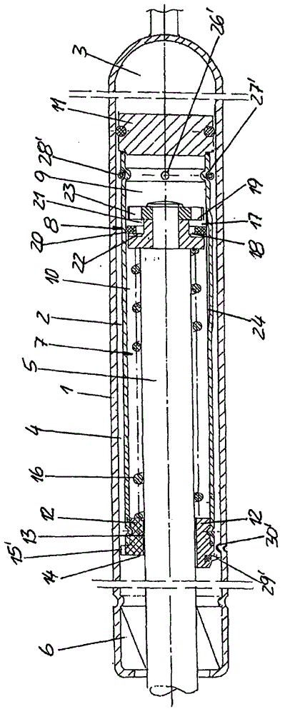
[0022] The tension spring shown in the figure has a cylinder 1 which is divided by a guide 2 into a gas chamber 3 filled with gas under pressure and a hydraulic chamber 4 filled with hydraulic fluid.

[0023] One end region of the guide part 2 is connected to a piston rod 5 which protrudes from the cylinder 1 through the hydraulic chamber 4 and a guide and sealing unit 6 , which seals this hydraulic chamber from the outside.

[0024] The guide 2 has an axially extending cylinder chamber 7 which is divided by a steam piston 8 into a steam chamber 9 adjacent to the gas chamber 3 and a spring chamber 10 remote from the gas chamber 3 .

[0025] The diameter of the steam piston 8 is smaller than the inner diameter of the cylinder chamber 7 .

[0026] The cylinder chamber 7 is also filled with hydraulic fluid and is connected to the inner chamber of the cylinder 1 , which is closed at its end side close to the gas chamber 3 by a bottom 11 . The end of the cylinder chamber 7 facing ...


PUM


Abstract

The tension spring has a cylinder (1) which is divided in a gas chamber (3) and a hydraulic chamber (4) by a piston, where the gas chamber is filled with a gas stands under pressure. The hydraulic chamber is filled with a hydraulic liquid. The piston is formed as a guide piece (2) which has a coaxially extended filled cylindrical chamber (7) filled with hydraulic liquid.

Description

technical field [0001] The invention relates to a tension spring with a cylinder, which is divided by a piston into a gas chamber filled with gas under pressure and a hydraulic chamber filled with hydraulic fluid; a piston rod connected to the piston, the piston rod Sealably protrudes from the cylinder through the hydraulic chamber. Background technique [0002] Such tension springs are used in particular for closing doors or flaps of furniture. [0003] Such tension springs have the disadvantage that they have a long construction length and thus require a large installation space. Contents of the invention [0004] It is therefore the object of the invention to provide a tension spring of the type mentioned at the outset, which has a short overall length and is of simple construction. [0005] According to the invention, this object is achieved in that the piston is a guide with a coaxially extending cylinder chamber filled with hydraulic fluid, in which a steam arrange...

Claims


Application Information

Patent Timeline
Patent Type & Authority Applications(China)
IPC IPC(8): F16F9/06F16F9/32F16F9/36F16F13/00
CPCF16F9/36F16F9/22F16F9/06F16F9/32F16F13/00F16F9/062E05F3/108E05Y2900/20F16F9/067F16F9/3235
Inventor H・波申
Owner STABILUS
Why Eureka
Try Eureka