Automatic feeding and discharging mechanism of jig

A technology for feeding and unloading materials and fixtures, which is applied in the direction of conveyors, coil manufacturing, electrical components, etc., can solve problems such as difficulty in widespread use, waste of raw materials, and low efficiency, so as to reduce the use of manpower, ensure material supply, and improve coordination. sexual effect

Active Publication Date: 2015-06-24
SHIN YUAN ELECTRONICS PROD KUNSHAN
View PDF4 Cites 0 Cited by
  • Summary
  • Abstract
  • Description
  • Claims
  • Application Information

AI Technical Summary

Problems solved by technology

However, the production efficiency of this manual winding machine is extremely low. According to the difference in inductance and unfamiliarity of personnel, the wound inductance coils are not the same, and there are large differences in the same product that is wound. At the same time, manual operation is also difficult. Leads to a lot of waste of raw materials, so hand-wound inductor coils are of unstable quality and poor performance
With the development of the electronics industry, computer numerical control winding machines have been widely used in the industrial field, but the structure of this multi-axis automatic winding machine is too complicated, resulting in high cost and high failure rate, and requires more than two people to operate Production, work efficiency is low, enameled wire waste is serious, it is difficult to widely popularize and use
[0004] As a fixture feeding and discharging mechanism used in conjunction with the inductance coil winding device, the current prior art requires manpower to complete the feeding and discharging of the fixture, which is inconvenient to operate, low in efficiency, high in cost, and the positioning of the fixture is not accurate, resulting in coil winding Deviations occur in the follow-up process, and the quality of the final inductive coil product is unstable and poor in performance. Therefore, a mechanism that can complete the automatic feeding and unloading and positioning of the jig is needed to solve various problems in the existing technology.

Method used


Image

  • Automatic feeding and discharging mechanism of jig
  • Automatic feeding and discharging mechanism of jig

Examples


Embodiment Construction

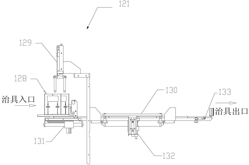
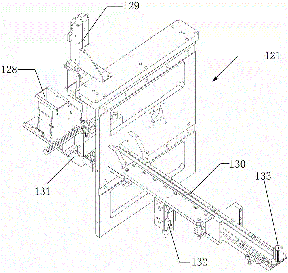
[0019] Please refer to figure 1 and figure 2 , figure 1 Shown is a schematic structural view of the jig automatic feeding and discharging mechanism in a preferred embodiment of the present invention, figure 2 Shown is a three-dimensional schematic view of the jig automatic feeding and discharging mechanism in a preferred embodiment of the present invention. The present invention proposes an automatic feeding and discharging mechanism for jigs, including: a feeding jig mechanism 121; a jig silo 128, which is arranged on the feeding jig mechanism 121 for feeding jigs; a feeding bin feeding cylinder 129 , set on the feeding jig mechanism 121 and above the jig bin 128; the bin advance cylinder 131, connected to the jig bin 128, is used to drive the jig to move; the discharge positioning mechanism 133 , connected to the feeding jig mechanism 121 , used to discharge the jig after the winding operation is completed.

[0020] According to a preferred embodiment of the present in...


PUM


Abstract

The invention provides an automatic feeding and discharging mechanism of a jig. The mechanism comprises a feeding jig mechanism, a jig bin, a bin distributing cylinder, a bin advancing cylinder and a discharging positioning mechanism, wherein the jig bin is arranged on the feeding jig mechanism and is used for jig feeding; the bin distributing cylinder is arranged on the feeding jig mechanism and is located above the jig bin; the bin advancing cylinder is connected to the jig bin and is used for driving the jig to move; and the discharging positioning mechanism is connected to the feeding jig mechanism and is used for discharging the jig after completing winding operation. The automatic feeding and discharging mechanism of the jig provided by the invention can automatically complete feeding and discharging of the jig wounded by an inductance coil and ensures material supply of a machine.

Description

technical field [0001] The invention relates to the field of inductance coil winding, and in particular to an automatic fixture feeding and discharging mechanism applied to inductance coil winding. Background technique [0002] The inductance coil is made of wires that are wound round by round on the insulating tube. The wires are insulated from each other, and the insulating tube can be hollow, or it can contain an iron core or a magnetic powder core, referred to as an inductance. The vast majority of electronic components, such as resistors, capacitors, speakers, etc., are finished products produced by the production department according to the specified standards and series for selection. However, only a part of the inductance coils, such as choke coils, low-frequency choke coils, oscillating coils, and LG fixed inductance coils, are products produced according to specified standards. Most of the inductance coils are non-standard parts, which are often based on actual nee...

Claims


Application Information

Patent Timeline
Patent Type & Authority Patents(China)
IPC IPC(8): H01F41/06B65G25/00H01F41/096
Inventor 郑吉宏王均哲
Owner SHIN YUAN ELECTRONICS PROD KUNSHAN
Why Eureka
Try Eureka