Solar cell compensation structure for mobile phone
A technology of solar cells and compensation structures, applied in circuits, photovoltaic power generation, electrical components, etc., can solve the problems of bulky and inconvenient solar mobile phone chargers, and heavy carrying of solar chargers, so as to enhance power generation efficiency and increase absorption rate , the effect of beautiful appearance
- Summary
- Abstract
- Description
- Claims
- Application Information
AI Technical Summary
Problems solved by technology
Method used
Image
Examples
Embodiment 1
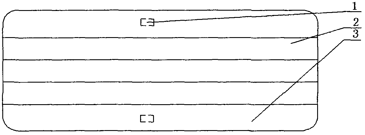
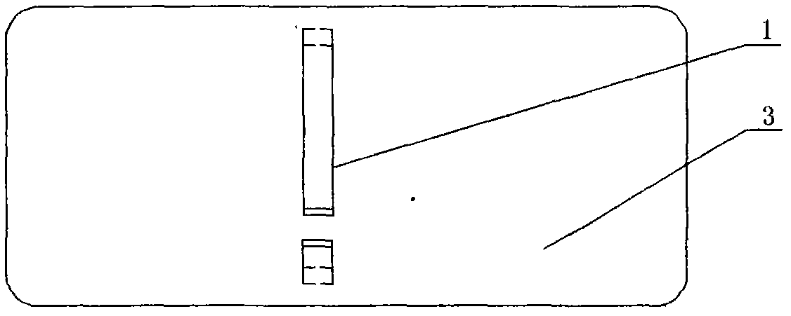
[0026] This embodiment discloses a mobile phone solar cell compensation structure by taking a straight mobile phone without a camera on the back shell as an example. The back shell is close to the battery electrodes of the mobile phone, and is located on both sides of the shell to penetrate the shell and integrate with the shell. The lead-out electrodes are flush with the shell surface on the outside of the shell, and inside the shell Connect with the mobile phone battery electrode to form a loop. Amorphous silicon thin-film solar cell units connected in an inline or outboard structure are arranged on the surface of the housing. An anti-reflection film layer is provided above the thin-film solar cell unit.
[0027] When the back shell of the mobile phone is exposed to light, the amorphous silicon thin-film solar cell absorbs the light to generate electricity, and the electric energy flows to the battery of the mobile phone through the lead-out electrodes to supplement the con...
Embodiment 2
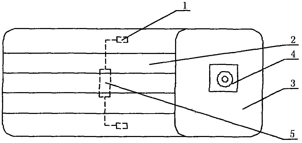
[0029] This embodiment discloses a mobile phone solar cell compensation structure by taking a flip phone with a camera on the back shell as an example. On the back shell surface where there is no camera and the battery of the mobile phone is installed, a lead-out electrode that penetrates the shell and is integrated with the shell is located on both sides of the shell. The lead-out electrode is flush with the surface of the shell on the outside of the shell. The inside of the casing is connected with the electrode seat of the mobile phone battery to form a loop, and a bypass diode is arranged beside the two lead-out electrodes, and the bypass diode and the lead-out electrodes form a path. CIGS thin-film solar cell units connected in an inline or outboard structure are arranged on the surface of the housing. An anti-reflection film layer is provided above the thin-film solar cell unit.
[0030] This embodiment is improved on the basis of the previous embodiment. Because half ...
Embodiment 3
[0032] This embodiment discloses a solar cell compensation structure for a mobile phone by taking the front shell of the netbook as an example. On both sides of the casing, there are lead-out electrodes that penetrate the casing and are integrated with the casing. The lead-out electrodes are flush with the surface of the casing on the outside of the casing, and are connected to the electrode holder of the netbook battery inside the casing. A loop is formed, and a bypass diode is arranged beside the two lead-out electrodes, and the bypass diode and the lead-out electrodes form a path. CIGS stacked thin film solar cell units connected in an inline or outboard structure are arranged on the surface of the casing, and the transparent conductive electrode adopts an ITO film layer. An anti-reflection film layer is provided above it.
[0033] Since the back shell of the netbook generally has many functional small holes, it is not conducive to film formation, and it is also not conduc...
PUM
 Abstract
Description
Claims
Application Information
 - R&D
- Intellectual Property
- Life Sciences
- Materials
- Tech Scout
- Unparalleled Data Quality
- Higher Quality Content
- 60% Fewer Hallucinations
Browse by: Latest US Patents, China's latest patents, Technical Efficacy Thesaurus, Application Domain, Technology Topic, Popular Technical Reports.
© 2025 PatSnap. All rights reserved.Legal|Privacy policy|Modern Slavery Act Transparency Statement|Sitemap|About US| Contact US: help@patsnap.com


