Magnetic field choked flow and resistive-inductive load power controller

A power controller, inductive load technology, applied in the direction of AC network circuits, electrical components, circuit devices, etc., can solve the problems of high current and voltage, waste of electric energy, load exceeding the rated power, etc., to prolong the service life and protect the safety. Effect

Inactive Publication Date: 2013-01-09
彭忠谏
View PDF4 Cites 0 Cited by
  • Summary
  • Abstract
  • Description
  • Claims
  • Application Information

AI Technical Summary

Problems solved by technology

[0002] In the current existing technology, the current and voltage in the circuit are too high, which will caus

Method used


Image

  • Magnetic field choked flow and resistive-inductive load power controller
  • Magnetic field choked flow and resistive-inductive load power controller
  • Magnetic field choked flow and resistive-inductive load power controller

Examples


Embodiment 1

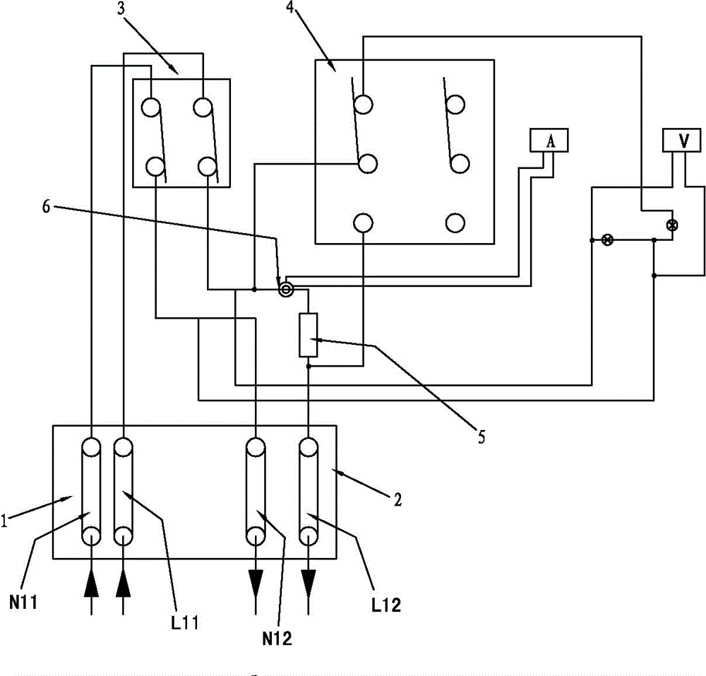
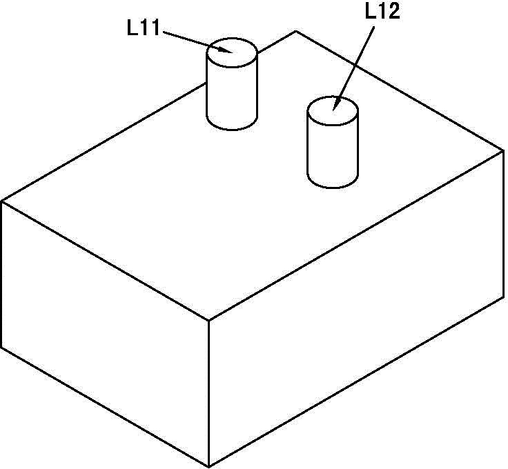
[0022] like figure 1 , figure 2 As shown in the figure, a magnetic field blocking current, resistive load power controller includes an incoming line end 1, a power switch 2 and an outgoing line end 3, including an energy-saving switch 4, the incoming line end 1 is connected to the input of the power switch 2, and the power switch The output end of 3 and the line of the outlet end 3 are provided with a magnetic field choke 5;

[0023] figure 1 and figure 2 Shown is a single-phase power circuit.

[0024] The incoming line end 1 is provided with an incoming line phase line column L11 and an incoming line zero line column N21, and the outgoing line end 2 is provided with an outgoing line phase line column L12 and an outgoing line zero line column N22;

[0025] The magnetic field resistor 5 is arranged on the phase line circuit between the output end of the power switch 3 and the phase line outlet pole L12.

[0026] The energy-saving switch 4 is connected in parallel with th...

Embodiment 2

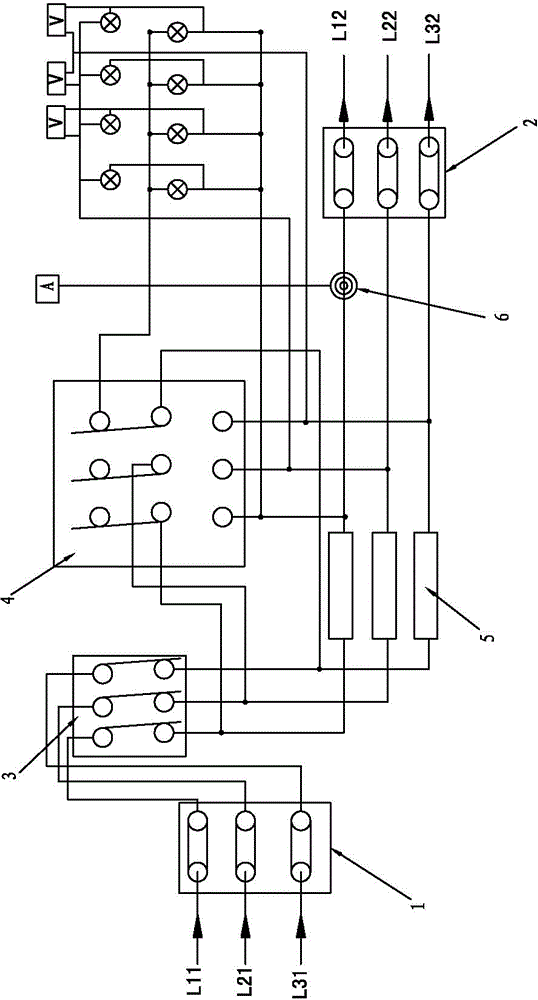
[0029] like image 3 , Figure 4 As shown, the incoming line end 1 is provided with a first incoming line phase line column L11, a second incoming line phase line column L21 and a third incoming line phase line column L31, and the outgoing line end is provided with a first outgoing line phase line column L12, the second outgoing line phase line column L22 and the third outgoing line phase line column L32;

[0030] The first incoming line phase line column L11, the second incoming line phase line column L21 and the third incoming line phase line column L31 are respectively connected to the power switch, and the output end of the power switch 2 is connected to the first outgoing line phase line column L12, the third A magnetic field choke 5 is arranged on the line between the phase line column L22 of the second outgoing line and the phase line column L32 of the third outgoing line.

[0031] When the energy-saving transfer switch 4 is in a certain state, when the neutral line o...

Embodiment 3

[0034] like Figure 5 , Image 6 As shown, it also includes a zero line, the incoming line end is provided with a zero line incoming line terminal N11, and the outgoing line end is provided with a zero line outgoing line terminal N12;

[0035] A magnetic energy choke 5 is arranged on the line between the zero line incoming terminal N11 and the neutral outgoing terminal N12 at the outgoing end, and an energy-saving switch 4 is connected in parallel with the magnetic field choke 5 .

[0036] like Figure 7 As shown, the magnetic field choke 5 includes an iron core and a coil. The iron core is circular or square.


PUM


Abstract

The invention provides a magnetic field choked flow and resistive-inductive load power controller, comprising a wire inlet end, a power supply switch and a wire outlet end, and further comprising an energy-saving conversion switch. The wire inlet end is connected with the power supply switch; a magnetic flow plug is arranged on a circuit of the power supply switch and the wire outlet end; one end of the circuit is connected with the output end of the power supply switch, and the other end of the circuit is connected with the wire outlet end; and the energy-saving conversion switch is connected in parallel with the magnetic flow plug. With the adoption of the structure, the choked flow requirement with large power can be met; the rated current flow-through load can be prevented, so that the electric devices do not work under a state of exceeding the rated current. Therefore, the security of the electric device can be effectively protected; and the service life of the electric device can be prolonged. The magnetic field choked flow and resistive-inductive load power controller can be used as an electricity saver.

Description

technical field [0001] The present invention relates to a power device, in particular to a load power controller. Background technique [0002] In the current prior art, the current and voltage in the circuit are too high, which will cause the load to exceed the rated power, resulting in damage to electrical equipment and waste of electrical energy. SUMMARY OF THE INVENTION [0003] The purpose of the present invention is to provide a magnetic field resistive, resistive load power controller, which can effectively prevent the overload power of the electrical appliance and protect the electrical appliance. [0004] The present invention is realized as follows: a magnetic field blocking current, resistive load power controller, including an incoming line end, a power switch and an outgoing line end, and its special feature is that it includes an energy-saving transfer switch, and the incoming line end is connected to the power switch , a magnetic field choke is arranged on ...

Claims


Application Information

Patent Timeline
IPC IPC(8): H02J3/00
Inventor 彭忠谏
Owner 彭忠谏
Why Eureka
Try Eureka