Smart switch and smart home system using the smart switch

A smart switch and gateway technology, applied in data processing applications, information technology support systems, electric power measurement by applying digital technology, etc., can solve problems such as not being able to satisfy users, unable to obtain power parameter information of electric equipment, and achieve satisfaction effect of demand

Active Publication Date: 2015-11-25
JIANGXI MINXUAN INTELLIGENT SCI & TECH
View PDF2 Cites 2 Cited by
  • Summary
  • Abstract
  • Description
  • Claims
  • Application Information

AI Technical Summary

Problems solved by technology

However, the existing switches are mainly used to control the power supply of electrical appliances / electrical equipment, and the relevant power consumption parameter information of the electrical equipment cannot be obtained.
Although some patent documents mention that the switch provided in the smart home system has the function of detecting and displaying the voltage, current, and power consumption of the electrical equipment, the user still cannot know the function of the electrical equipment through the switch connected to the electrical equipment. Information such as the power consumption consumed by electrical equipment, therefore, the existing switches cannot meet the needs of users

Method used


Image

  • Smart switch and smart home system using the smart switch
  • Smart switch and smart home system using the smart switch
  • Smart switch and smart home system using the smart switch

Examples


Embodiment Construction

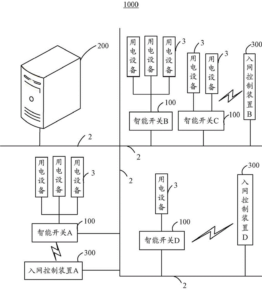
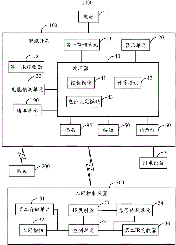
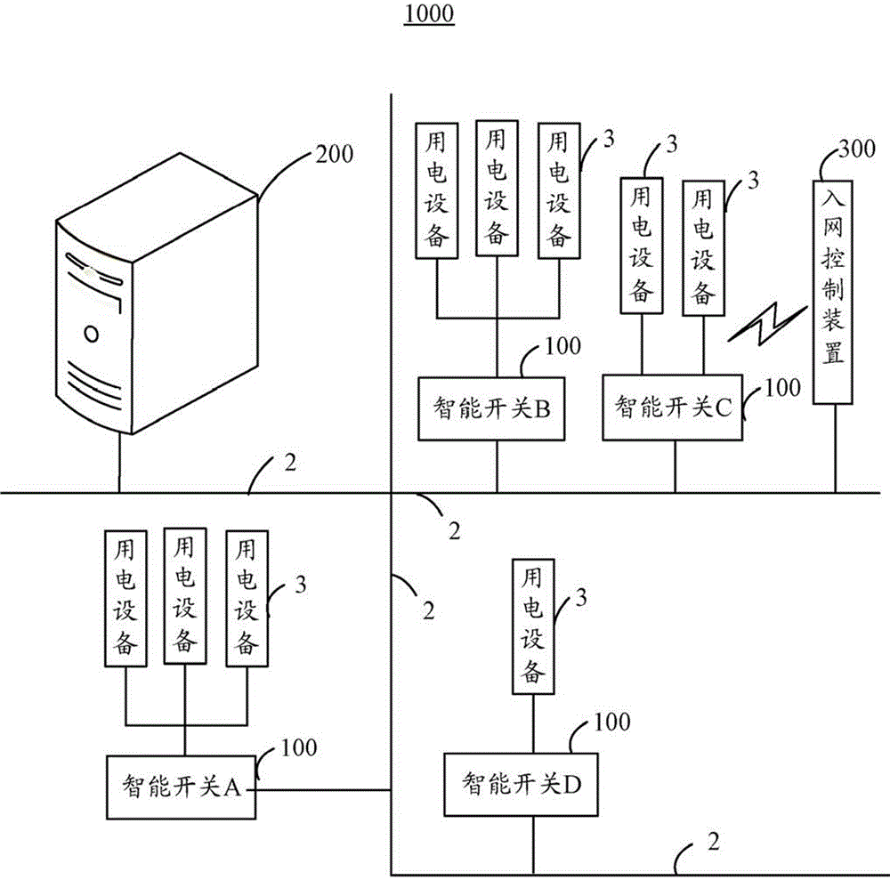
[0017] Please also refer to Figure 1-Figure 2 ,in, figure 1 It is a schematic diagram of a smart home system 1000 to which the smart switch 100 of the present invention is applied, figure 2 It is a functional block diagram of a smart home system 1000 to which the smart switch 100 of the present invention is applied. The smart home system 1000 includes at least one smart switch 100, a gateway 200 connected to the smart switch 100 through the power line 2, at least one network access control device 300 connected to the gateway 200 through the power line 2 (optical fiber cable), and at least one connected to the smart switch. 100 of electrical equipment 3. Each room in the smart home system 1000 is provided with a network access control device 300 . In this embodiment, the smart switch 100 and the gateway 200, the gateway 200 and the network access control device 300 are connected by wired or wireless means, such as PLC (PowerLine Communication, power line communication) thr...


PUM


Abstract

A smart switch applied to a smart home system is connected to a power supply and at least one electronic device. The smart switch includes a screen, a power detecting unit configured to detect real-time electrical information of the electronic device, a processor unit including a calculating module configured to calculate total electricity consumption of the electronic device and a control module configured to control the screen to display instantaneous electrical information and the total electricity consumption, and a communication unit configured to connect the smart switch to a gateway of the smart home system in wired or wireless manner, and send the electrical information and the total electricity consumption to the gateway. A smart home system is also provided.

Description

technical field [0001] The invention relates to an intelligent switch and an intelligent home system using the intelligent switch. Background technique [0002] Existing switches are usually arranged on the wall or on the ground, and users can control the power supply of home appliances / various electrical appliances by controlling the switches. Some switches are equipped with sockets and indicator lights, and the indicator lights can be used to indicate the power status of the corresponding sockets. However, the existing switches are mainly used to control the power supply of electrical appliances / electrical equipment, and cannot obtain relevant power consumption parameter information of the electrical equipment. Although some patent documents mention that the switch provided in the smart home system has the function of detecting and displaying the voltage, current, and power consumption of the electrical equipment, but the user still cannot know the function of the electri...

Claims


Application Information

Patent Timeline
Patent Type & Authority Patents(China)
IPC IPC(8): H04L12/28
CPCG01R21/133G01R22/063G06Q50/06G06F2200/261Y02B90/20Y02D10/00Y04S20/30
Inventor 陈德胜李晓光谢冠宏肖昀皮尚慧
Owner JIANGXI MINXUAN INTELLIGENT SCI & TECH
Why Eureka
Try Eureka