Stamping part clamp

A technology for stamping fixtures and plastic clamps, applied in the field of stamping fixtures

Inactive Publication Date: 2013-01-16
KUNSHAN JIZHICHENG MOLD
View PDF5 Cites 4 Cited by
  • Summary
  • Abstract
  • Description
  • Claims
  • Application Information

AI Technical Summary

Problems solved by technology

[0002] At present, in the manufacturing process of stamping parts, manual operation is generally used when picking and placing stamping parts. Safety accidents, in the prior art, ferromagnet fixtures are used to pick and place stamping parts, but during use, ferromagnet fixtures are convenient to absorb directly when taking them out, but when putting them in, they need to use force or use foreign objects It is inconvenient to remove, which affects the efficiency of picking and placing stamping parts

Method used


Image

  • Stamping part clamp

Examples


Embodiment Construction

[0013] The present invention will be further described below in conjunction with the accompanying drawings.

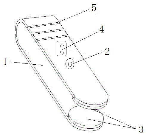
[0014] Such as figure 1 As shown, a clamp for stamping parts includes a U-shaped plastic clamp body 1. The surface of the rear end of the plastic clamp body 1 is also provided with an anti-slip groove 5, which is convenient to hold and has an anti-slip function. The plastic clamp body 1 There is a button battery 4 inside, which is used to pass the operating voltage to the electromagnet 3. The electromagnet 3 is installed on the inside of the front end of the plastic clip body 1 close to the opening, because the cylindrical electromagnet 3 is very common, easy to obtain, and cheap. The shape of electromagnet 3 is selected as cylindrical, beautiful in appearance, and the outer surface of plastic clip body 1 is provided with power switch 2, and button cell 4 is connected with the lead-out end of electromagnet 3 through power switch 2, when taking stamping parts, Press t...


PUM


Abstract

The invention discloses a stamping part clamp which comprises a U-shaped plastic clamp body (1), wherein a button cell (4) is arranged in the plastic clamp body (1), an electromagnet (3) is installed on the inside (close to an opening) of the front end of the plastic clamp body (1), a power switch (2) is arranged on the external surface of the plastic clamp body (1), the button cell (4) is connected with a wire lead-out end of the electromagnet (3) by the power switch (2), and an antislip groove (5) is also arranged on the surface of a holding part at the rear end of the plastic clamp body (1). The clamp is used for taking and putting a stamping part, the electromagnet is arranged on the inside of the clamp, the switch which controls the electromagnet to own magnetism or not is arranged on the outside of the clamp and can control the magnetism of the electromagnet at any time, the stamping part taking and putting efficiencies are improved, and the clamp is simple in structure, is easy to implement and has a good application prospect.

Description

technical field [0001] The invention relates to the technical field of stamping fixtures, in particular to a fixture for picking and placing stampings. Background technique [0002] At present, in the manufacturing process of stamping parts, manual operation is generally used when picking and placing stamping parts. Under negligent operation, it is easy to cause harm to the human body and cause safety accidents. In the prior art, iron magnet clamps are used to realize stamping. However, during the use of the ferromagnet fixture, it is very convenient to directly absorb it when it is taken out, but when it is placed, it needs to be removed with force or with the help of foreign objects, which is inconvenient and affects the efficiency of picking and placing stamping parts. Contents of the invention [0003] The purpose of the present invention is to overcome the deficiencies in the prior art, and provide a fixture for picking and placing stamping parts. An electromagnet is...

Claims


Application Information

Patent Timeline
Patent Type & Authority Applications(China)
IPC IPC(8): B25B9/02
Inventor 刘志泳
Owner KUNSHAN JIZHICHENG MOLD
Why Eureka
Try Eureka