Method for manufacturing exhaust passage

A technology for exhaust ducts and bottom molds, applied in the manufacture of tools, ceramic molding machines, etc., can solve the problems of easy sliding down, high technical proficiency requirements for production workers, and easy sliding down, etc., to achieve low technical proficiency, Wall thickness is easy to control Uniform and easy to control effect

Active Publication Date: 2015-06-03
GUANGZHOU CAIDIE ENERGY SAVING TECH +1
View PDF9 Cites 0 Cited by
  • Summary
  • Abstract
  • Description
  • Claims
  • Application Information

AI Technical Summary

Problems solved by technology

Long-term practice has proved that this traditional exhaust duct molding process has the following defects: (l) It requires high technical proficiency for production workers; The release agent becomes very slippery, and the cement mortar is easy to slip off after being applied. The production workers must undergo a long period of training to complete this difficult operation; (2) The wall thickness of the exhaust duct is not easy to control and uniform ;Because the side mortar of the exhaust duct is easy to slide down, its wall thickness uniformity largely depends on the operator's technical proficiency and sense of responsibility, it is difficult to ensure the consistency of the side wall thickness, and the product quality cannot be truly controlled , there is no guarantee that its dimensional tolerances and mechanical performance indicators meet the requirements of the national industry standard "Residential Kitchen and Bathroom Exhaust Duct" JG / T194-2006
Practice has proved that this preparation method still has the following defects: the preparation process needs to strictly control the time of rotating the corresponding mold before the initial setting of the cementitious material, and the preparation process is not easy to control

Method used


Image

  • Method for manufacturing exhaust passage
  • Method for manufacturing exhaust passage
  • Method for manufacturing exhaust passage

Examples


Embodiment 1

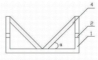
[0030] like Figure 1-Figure 6 A schematic diagram of the fabrication process of the exhaust duct is shown, Figure 7-Figure 10 Schematic diagram of the removal process of the exhaust duct.

[0031] The exhaust duct preparation process of this embodiment includes:

[0032] 1) if figure 1 As shown, the bottom mold fixing frame 1 with the V-shaped bottom mold 4 is placed horizontally, wherein the two sides of the bottom mold fixing frame 1 are respectively provided with supporting feet 2;

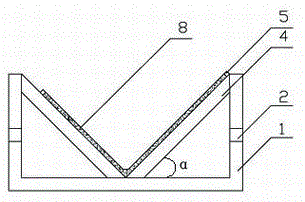
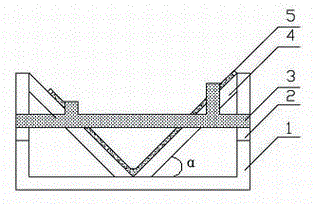
[0033] 2) if figure 2 As shown, the wall thickness positioning strip 5 is selected according to the wall thickness, side length and length of the exhaust duct to be prepared and placed on the corresponding positions at the sides and two ends of the two inner surfaces of the V-shaped bottom mold 4 On, spray release agent, smear the gel material between the wall thickness positioning strips 5 on the two inner sides of the V-shaped bottom mold 4, and scrape the gel material with a V-shaped...

Embodiment 2

[0043] The exhaust duct preparation process of this embodiment includes:

[0044] Steps 1)-8) are the same as in Example 1;

[0045] 9) if Figure 11 As shown, after removing the positioning bar 5, directly take out the exhaust duct 8 with the top mold 7;

[0046] 10) If Figure 12 As shown, the top mold 7 is taken out to obtain the exhaust duct 8, which can be maintained.

Embodiment 3

[0048] The exhaust duct preparation process of this embodiment includes:

[0049] 1) Place the bottom mold fixing frame 1 with the V-shaped bottom mold 4 on the horizontal surface, set the wall thickness positioning strips 5 on the inner sides of the V-shaped bottom mold 4, and the wall thickness positioning strips 5 prepare the sides of the exhaust duct according to the needs length, length and wall thickness are selected and placed on the sides of the two inner surfaces of the bottom mold 4 and the corresponding positions at the two ends;

[0050] 2) Spray the release agent, and then apply the gelling material between the wall thickness positioning strips 5 on the two inner sides of the V-shaped bottom mold 4, and scrape it flat with a V-shaped scraper;

[0051] 3) After the gelling material is finally set, remove the positioning strip and take out the exhaust duct assembly;

[0052] 4) Repeat the above steps to prepare another exhaust duct assembly;

[0053] 5) Glue the t...


PUM


Abstract

The invention relates to a method for manufacturing an exhaust passage for eliminating kitchen fume and bathroom waste gas. The method for manufacturing the exhaust passage includes respectively smearing gel material on two inner sides of a V-shaped bottom form and two outer sides of a reverse-V-shaped top form matched with the V-shaped bottom form. Forms in the manufacturing process are V-shaped, and the method requires no vertical plastering forming compared with the conventional forming process for the exhaust passage, so that the requirement for technical skilled degree of production workers is low, labor is saved, and the wall depth of the exhaust passage is easy to evenly control. Compared with a subsequently-modified method for manufacturing an integrated residential exhaust passage by a rotatably foldable form, the method requires no rotation of any form in manufacturing process, and accordingly the time for rotating a corresponding form need not be controlled. Therefore, the method for manufacturing the exhaust passage is easy to control, convenient to use and convenient for popularization of large-scale industrialization.

Description

technical field [0001] The invention relates to a preparation method of an exhaust duct for removing kitchen oil fume and toilet waste gas. Background technique [0002] The exhaust duct is mainly used to collect kitchen fume and bathroom exhaust gas. With the development of urban construction and the increase of residential construction, the demand for exhaust ducts is also increasing. [0003] The current residential exhaust ducts are basically formed by the traditional process: first, erect two side forms on the ground, use the ground between the side forms as the bottom form, and paint the surfaces of the bottom form and the side form A layer of release agent, followed by a layer of cement mortar by hand, followed by a layer of reinforcing material, and a layer of cement mortar, the bottom surface and two sides of the exhaust duct are formed in this way; then, between the side molds The top mold is supported between the top molds, and the cement mortar and reinforcemen...

Claims


Application Information

Patent Timeline
Patent Type & Authority Patents(China)
IPC IPC(8): B28B21/00
Inventor 聂法玉谭源生
Owner GUANGZHOU CAIDIE ENERGY SAVING TECH
Why Eureka
Try Eureka