High-temperature dust-removing and filtering sleeve and preparation method thereof

A technology of high-temperature dust removal and dust removal pipes, applied in separation methods, dispersed particle filtration, chemical instruments and methods, etc., can solve the problem of reducing the filtration speed of filter materials, affecting the effect and efficiency of high-temperature flue gas and dust purification, and increasing the size of filter materials Air resistance and other issues, to achieve the effect of good dust removal effect

Active Publication Date: 2018-10-19
LUYANG ENERGY SAVING MATERIALS CO LTD
View PDF6 Cites 3 Cited by
  • Summary
  • Abstract
  • Description
  • Claims
  • Application Information

AI Technical Summary

Problems solved by technology

[0005] However, the surface pore diameter of the filter material is small, and coarse dust, medium dust, and fine dust are all blocked on the surface of the filter material to form "surface filtration", which virtually increases the air permeability resistance of the filter material and reduces the filtration speed of the filter material. , thus affecting the effect and efficiency of high temperature flue gas and dust purification

Method used


Image

  • High-temperature dust-removing and filtering sleeve and preparation method thereof
  • High-temperature dust-removing and filtering sleeve and preparation method thereof
  • High-temperature dust-removing and filtering sleeve and preparation method thereof

Examples


preparation example Construction

[0074] The present invention also provides a method for preparing the high-temperature dust-removing filter casing described in the above-mentioned technical solution, comprising the following steps:

[0075] a) mixing 100 parts by weight of ceramic fibers with water, beating, diluting and removing slag in sequence, and then uniformly mixing with 3 to 10 parts by weight of an organic binder and 5 to 20 parts by weight of an inorganic binder to obtain a slurry; Then the obtained slurry is formed, dehydrated and dried in sequence to obtain a blank; after processing, the first dust removal pipe is obtained;

[0076] b) Mix 100 parts by weight of ceramic fibers, 10 to 35 parts by weight of a pore control agent with water, perform beating, dilution and deslagging in sequence, and then mix 3 to 10 parts by weight of an organic binder, 5 to 20 parts by weight of The inorganic binder is evenly mixed to obtain a slurry; then the obtained slurry is sequentially molded, dehydrated and dr...

Embodiment 1

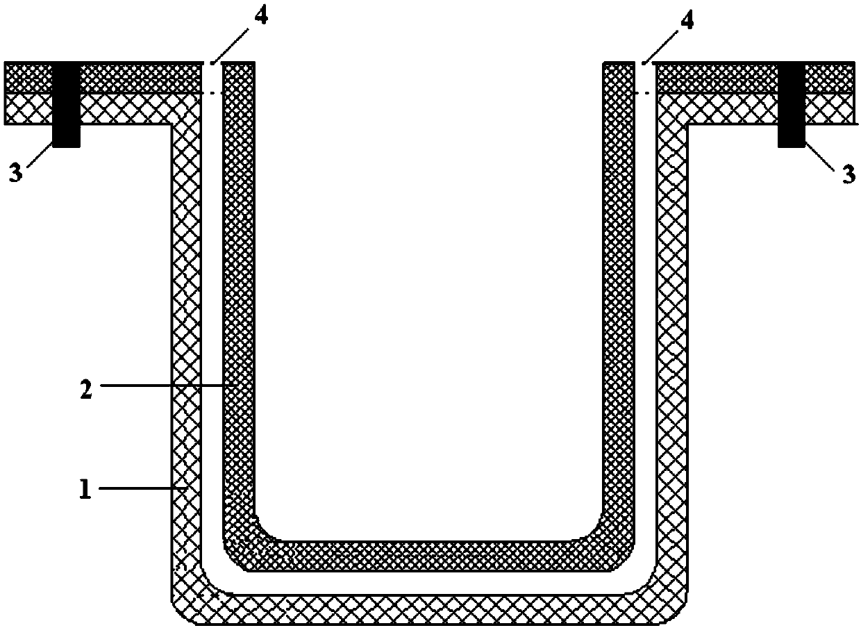
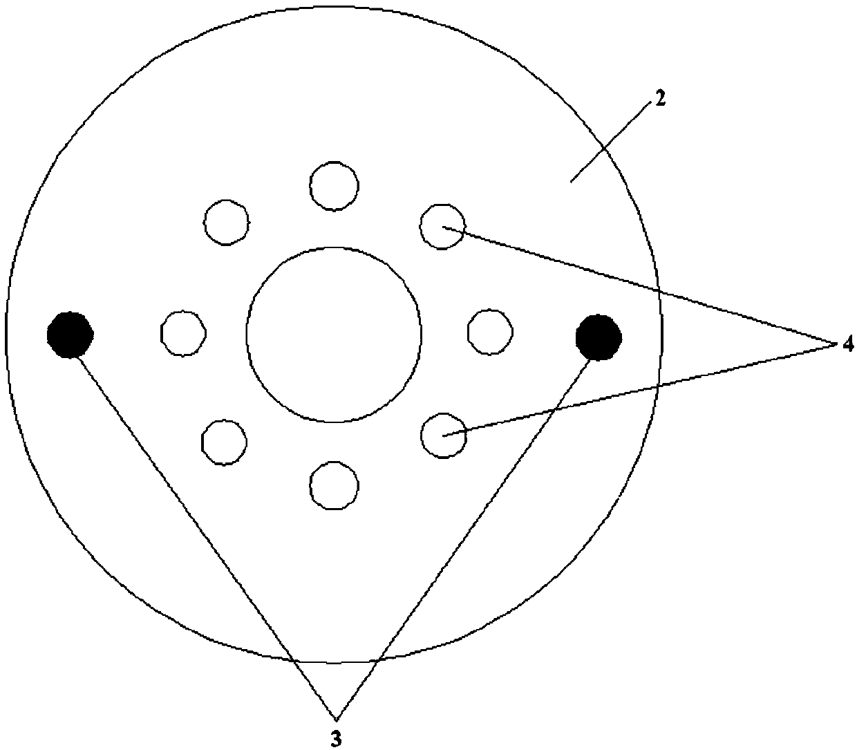
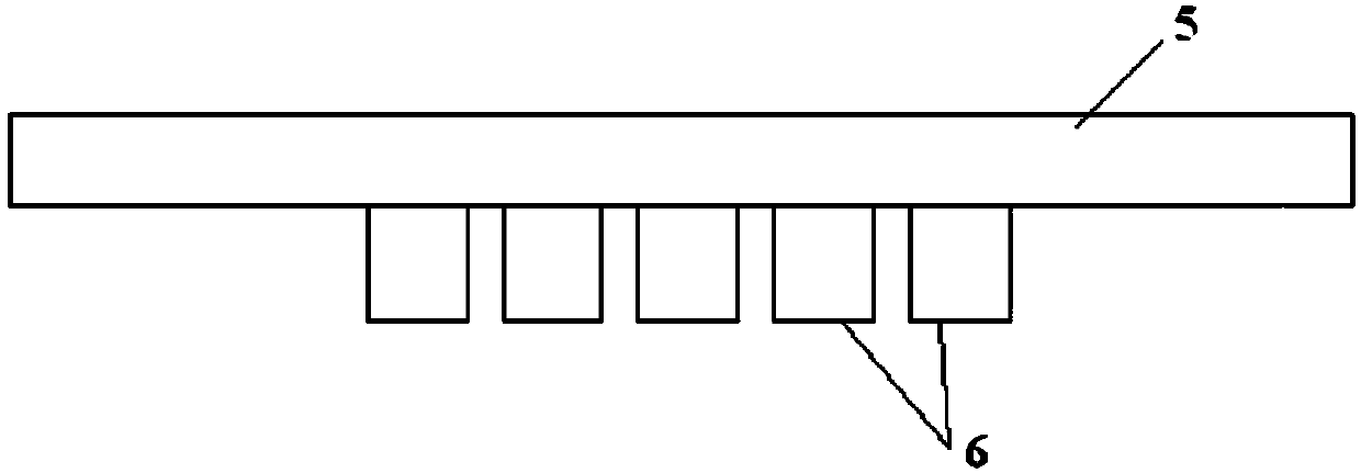
[0097] The schematic diagram of the structure of the high-temperature dust removal filter sleeve provided by Embodiment 1 of the present invention is as follows Figure 1~3 shown; among them, figure 1 The sectional view of the high-temperature dust removal filter casing provided for embodiment 1, figure 2 The top view of the high-temperature dust removal filter casing provided for embodiment 1, image 3 A cross-sectional view of the plug used in the high-temperature dust removal filter sleeve provided in Example 1. Figure 1~3 Among them, 1 is the first dust removal pipe, 2 is the second dust removal pipe, 3 is the bolt, 4 is the exhaust hole, 5 is the plug cover, and 6 is the exhaust hole plug. Wherein, the wall thickness of the first dust removal casing is 20mm, the inner diameter is 160mm, the outer diameter is 200mm, and the outer diameter of the ring plane is 240mm; the wall thickness of the second dust removal casing is 20mm, the inner diameter is 100mm, and the outer...

Embodiment 2

[0102] The schematic diagram of the structure of the high-temperature dust removal filter sleeve provided by Embodiment 2 of the present invention is as follows Figure 1~3 shown; among them, figure 1 The sectional view of the high-temperature dust removal filter casing provided for embodiment 2, figure 2 The top view of the high-temperature dust removal filter casing provided for embodiment 2, image 3 A cross-sectional view of the plug used in the high-temperature dust removal filter sleeve provided in Example 2. Figure 1~3 Among them, 1 is the first dust removal pipe, 2 is the second dust removal pipe, 3 is the bolt, 4 is the exhaust hole, 5 is the plug cover, and 6 is the exhaust hole plug. Wherein, the wall thickness of the first dust removal casing is 20mm, the inner diameter is 160mm, the outer diameter is 200mm, and the outer diameter of the ring plane is 240mm; the wall thickness of the second dust removal casing is 20mm, the inner diameter is 100mm, and the outer...


PUM

PropertyMeasurementUnit
pore sizeaaaaaaaaaa
pore sizeaaaaaaaaaa
thicknessaaaaaaaaaa

Abstract

The invention provides a high-temperature dust-removing and filtering sleeve. The high-temperature dust-removing and filtering sleeve comprises a first dust-removing pipe, a second dust-removing pipeand a plug, wherein a bottom-end pipe opening of the first dust-removing pipe is inward sealed to form a blind hole, and a top-end pipe opening of the first dust-removing pipe extends outward to forman annular plane; the porosity of the first dust-removing pipe is 85 percent to 95 percent and the pore diameter of air pores is 30 mum to 50 mum; the second dust-removing pipe is embedded into the first dust-removing pipe; the bottom-end pipe opening of the second dust-removing pipe is inward sealed to form a blind hole, and the top-end pipe opening of the second dust-removing pipe extends outward to form an annular plane; the outer diameter of the second dust-removing pipe is smaller than the inner diameter of the first dust-removing pipe and a cavity is formed; a plurality of exhausting holes, which penetrate through the cavity, are formed in the annular plane of the second dust-removing pipe; the porosity of the second dust-removing pipe is 75 percent to 85 percent and the pore diameter of the air pores is 10 mum to 30 mum; the plug is used for sealing the second dust-removing pipe; the plug is provided with exhausting hole plugs corresponding to the exhausting holes. The high-temperature dust-removing and filtering sleeve provided by the invention adopts a specific structure and rapid and deep filtering can be realized; when being used for purifying high-temperature flue gas and dust, the high-temperature dust-removing and filtering sleeve has a relatively good effect and relatively high efficiency.

Description

technical field [0001] The invention relates to the technical field of high-temperature flue gas and dust purification, and more specifically relates to a high-temperature dust removal filter sleeve and a preparation method thereof. Background technique [0002] At present, my country's dust removal technology system is facing the second revolution in the field of high-temperature flue gas and dust purification technology. One of its important technical measures is the use of filter dust removal technology. In recent years, with the unremitting efforts of scientific researchers, filtration and dust removal technology has made great progress. [0003] The Chinese patent with the publication number CN1792412A discloses a ceramic-based composite material filter tube for cleaning high-temperature gas flue gas and its preparation method. The filter tube has a blind hole at one end and an open end, and the silicon carbide ceramic is toughened by continuous aluminum silicate fibers...

Claims


Application Information

Patent Timeline
Patent Type & Authority Applications(China)
IPC IPC(8): C04B28/24C04B28/00C04B38/00B01D46/00B01D46/24
CPCB01D46/0001B01D46/2403C04B28/005C04B28/24B01D46/64C04B14/4656C04B24/38C04B38/0074C04B38/0054C04B38/00C04B14/043C04B22/064C04B14/066
Inventor 刘超任大贵张成岳耀辉
Owner LUYANG ENERGY SAVING MATERIALS CO LTD
Why Eureka
Try Eureka