Conveying device

A technology of conveying device and driving device, applied in the field of plastic processing machinery, can solve the problems of low efficiency, slow change of spacing, complicated control, etc., and achieve the effect of accurate spacing, changing power mode and reducing overall volume

Active Publication Date: 2013-01-16
台州迈格机械模具有限公司
View PDF4 Cites 7 Cited by
  • Summary
  • Abstract
  • Description
  • Claims
  • Application Information

AI Technical Summary

Problems solved by technology

[0003] The present invention aims to solve one of the technical problems of the conveying device in the prior art, such as slow speed of changing pitch, low efficiency, complicated control,

Method used


Image

  • Conveying device
  • Conveying device
  • Conveying device

Examples


Embodiment 1

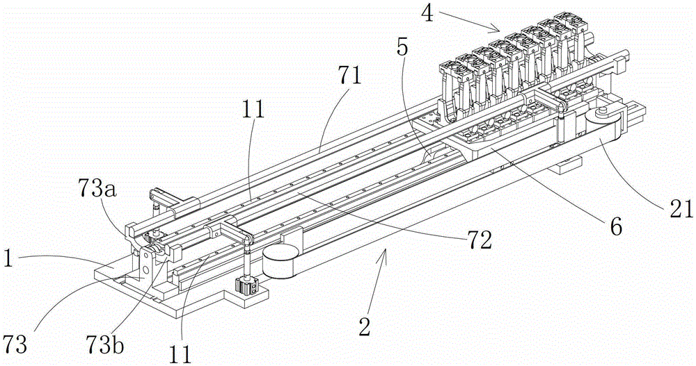
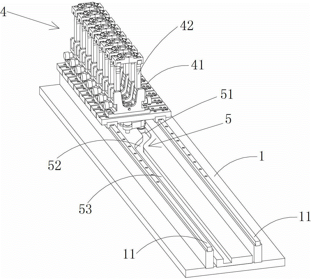
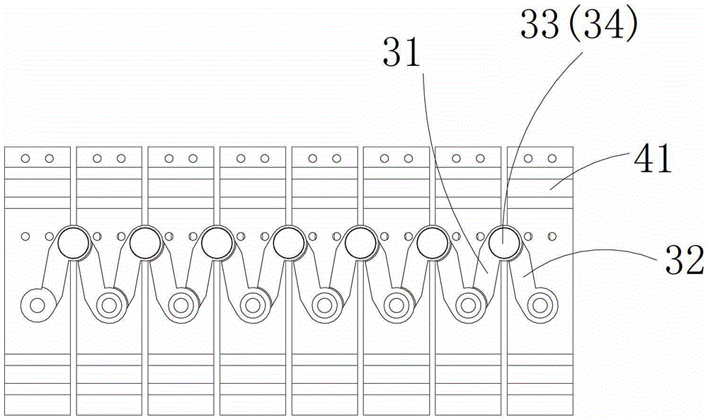
[0030] Such as Figure 1-8 As shown, a conveying device includes a base 1, a group of manipulators mounted on the base 1 that can reciprocate along the transmission path, a driving device 2 that drives the reciprocating movement of the manipulator group, and each manipulator 4 includes a manipulator seat 41 and the clamping portion 42 installed on the manipulator base 41, the adjacent two manipulator bases 41 are connected by the linkage mechanism 3, as image 3 , 4 As shown, the linkage mechanism 3 is two connecting rods 31 and 32, one end of the two connecting rods 31 and 32 are respectively pivotally connected to the bottoms of two adjacent manipulator seats 41, and the other ends are pivotally connected together to form a movable hinge point 33, A first bearing 34 is provided at the movable hinge point 33, and a displacement track 5 is provided on the base 1 and below the manipulator seat 41 to move the movable hinge point 33 so that two adjacent manipulators move relativ...

Embodiment 2

[0037] Such as Figure 8 As shown, the difference between this embodiment and Embodiment 1 is that the displacement track is a linear track 8 arranged below the manipulator seat 41, and the linear track 8 is connected to the base 1 through a cylinder and can be moved in the cylinder. Driven to move perpendicular to the transmission direction, a first bearing 34 is arranged at the living hinge point 33, and the first bearing 34 runs in the linear track 8.

[0038] The working process of this embodiment differs from that of Embodiment 1 in that: when the heating is completed, several manipulators (generally determined according to the number of cavities in the mould) hold the preform and enter the linear track 8, the cylinder moves, Pull the linear track 8 to move perpendicular to the transmission direction, drive the first bearing 34 inside to move, the connecting rods between several manipulators are opened at the same time, and a group of plastic container preforms realize pi...

Embodiment 3

[0040] The difference between this embodiment and Embodiment 1 is that it further includes a moving base 9 on which a group of manipulators 4 are arranged and connected with the driving device 2 through the moving base 9 . The upper surface of the moving seat 9 has a pair of second linear guide rails 91 arranged in parallel, and the lower surface has a pair of second slide blocks 92 corresponding to the pair of linear guide rails. A slider 41a is slidably connected to the second linear guide rail 91, and the moving base 9 is slidably connected to the first linear guide rail 11 on the base through the second slider 92. The bottom of the moving base 9 has an opening, and the linkage The mechanism 3 is connected to the shifting track 5 through the opening, and the shifting track 5 includes a first straight line segment 51, a shifting segment 52 and a second straight line segment 53 in sequence, and the first straight line segment 51 and the second straight line segment 53 are abse...


PUM


Abstract

The invention discloses a conveying device, which belongs to the technical field of plastic processing machinery. The conveying device comprises a base, a group of mechanical hands and a driving device, wherein the group of mechanical hands is arranged on the base, and can move in a reciprocating way along a conveying path; and the driving device is used for driving the mechanical hands to move in a reciprocating way. The conveying device is characterized in that each mechanical hand comprises a mechanical hand seat and a clamping part arranged on the mechanical hand seat; two adjacent mechanical hand seats are connected with each other through a linkage mechanism, and the middle part of the linkage mechanism is provided with at least one movable hinge joint; the base is provided with a moving track which can be used for moving the movable hinge point to drive the two adjacent mechanical hand seats to move relatively; the at least one movable hinge point is provided with a connecting piece; and the movable hinge point is connected with the moving track through the connecting piece. Due to the adoption of the conveying device, continuous and rapid operation of conveying and distance changing are realized, operation is easy, and the production efficiency is high.

Description

technical field [0001] The invention relates to a conveying device, in particular to a conveying device for transporting plastic container preforms on different processing stations, and belongs to the technical field of plastic processing machinery. Background technique [0002] All kinds of plastic containers such as water bottles, cosmetic bottles, medicine bottles, etc. are widely used in daily life, medicine, chemical industry and other fields. During processing, each preform enters from the billet inlet, and after being heated by the heating device, it is transported to the mold by the conveying device for blow molding. In order to improve the heat utilization rate, the preforms are arranged as closely as possible in the heating tunnel when they are heated in the heating device. When they leave the drying tunnel, the distance between the preforms needs to be increased mechanically or manually to match the multi-cavity mold. The distance between the moulds is kept consi...

Claims


Application Information

Patent Timeline
IPC IPC(8): B29C31/08
Inventor 蔡佳翰
Owner 台州迈格机械模具有限公司
Why Eureka
Try Eureka