Medium-frequency induction heating machine for glass molds

A technology of induction heating and glass mould, which is applied in glass forming, glass pressing, glass manufacturing equipment, etc., to achieve the effect of saving energy and reducing quantity

Active Publication Date: 2013-01-16
ORI MOLD TECH SUZHOU
View PDF3 Cites 1 Cited by
  • Summary
  • Abstract
  • Description
  • Claims
  • Application Information

AI Technical Summary

Problems solved by technology

[0007] However, the technical solution recommended by CN201039510Y above has the following disadvantages: since the advance and retreat oil cylinder and the lifting oil cylinder need to be used in the process of mold preheating, firstly the advance and retreat oil cylinder makes the preheated The hot mold enters or exits the lower position corresponding to the heating chamber of the intermediate frequency heating device in a horizontal motion, and then the preheated mold is lifted into the aforementioned heating chamber or exits the heating chamber in a vertical motion by the lifting cylinder. Therefore, it not only increases the number of power mechanisms, but also is not conducive to energy saving, because the work of advancing and retreating and lifting oil cylinders needs to be supported by the power supply. In addition, since each preheating is performed, the preheated mold needs to be translated step by step from left to right and up and down once , so there are many action links, which affect the operation efficiency, that is, it is not enough to increase the output of mold preheating per unit time, resulting in the risk of slowdown in the subsequent spray welding work
[0008] The applicant believes that the reason for the above-mentioned shortcoming is that the mold is in a dynamic state while the medium frequency induction heating box is in a static state during the heating process of the mould, that is to say, due to Lack of a reasonable medium frequency induction heating box lifting mechanism that allows the medium frequency induction heating box to move up and down relative to the mold

Method used


Image

  • Medium-frequency induction heating machine for glass molds

Examples


Embodiment Construction

[0014] In order to enable the examiners of the patent office, especially the public, to understand the technical essence and beneficial effects of the present invention more clearly, the applicant will describe in detail the following in the form of examples, but none of the descriptions to the examples is an explanation of the solutions of the present invention. Any equivalent transformation made according to the concept of the present invention which is merely formal but not substantive shall be regarded as the scope of the technical solution of the present invention.

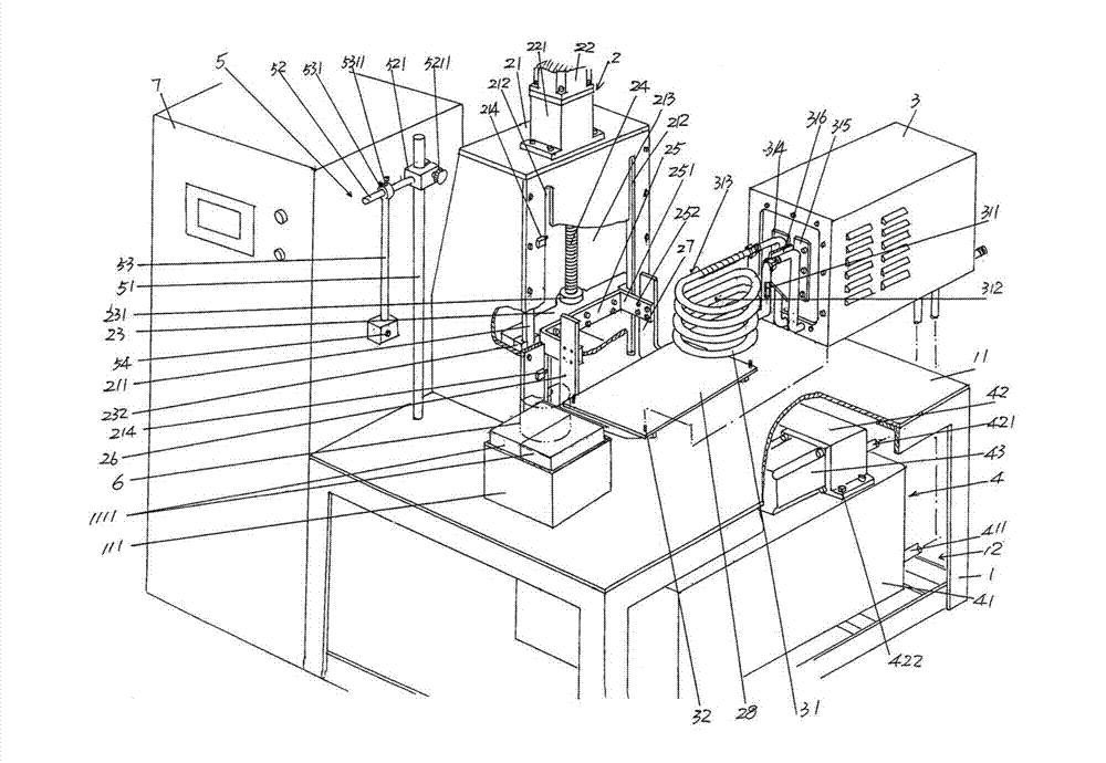
[0015] See figure 1 , a frame 1 is given, and the geometric shape of the frame 1 is not limited by the illustration. Taking the frame 1 of the structure of this embodiment as an example, a panel structure is formed on the upper end of the frame 1. A flat (flat) machine platform 11 has a mold seat 111 fixed on the machine platform 11, that is, the surface of the machine platform 11. When in use, a refract...


PUM

PropertyMeasurementUnit
thicknessaaaaaaaaaa
overlap rateaaaaaaaaaa

Abstract

The invention discloses a medium-frequency induction heating machine for glass molds, and belongs to the technical field of auxiliary facilities for glass mold manufacture. The medium-frequency induction heating machine comprises a frame, wherein the top end of the frame forms a machinery platform; the lower part of the machinery platform forms a water circulation cooling mechanism cavity; a mold mounting base is arranged on the surface of the machinery platform; a lifting mechanism of a medium-frequency induction heating box is fixed on the machinery platform; the medium-frequency induction heating box is erected on the lifting mechanism of the medium-frequency induction heating box; a coil of the medium-frequency induction heating box is positioned outside the medium-frequency induction heating box; and the coil is formed into a coil pipe shape. The medium-frequency induction heating machine is characterized in that the lifting mechanism of the medium-frequency induction heating box comprises a lifting rack, a motor, a sliding table, a screw, a fork foot rack, a first fork foot, a second fork foot and an induction box layer board, wherein the lifting rack is provided with a rack cavity. The medium-frequency induction heating machine has the advantages that the amount of power devices is reduced, the energy saving is embodied, and the movement links are reduced significantly, so that convenience is brought for improving the operation efficiency.

Description

technical field [0001] The invention belongs to the technical field of auxiliary facilities for manufacturing glass molds, and in particular relates to a medium-frequency induction heating machine for glass molds. Background technique [0002] The aforementioned intermediate frequency induction heating heats molds made of magnetically permeable materials such as carbon steel (also known as mold steel in the industry), copper alloys, and stainless steel in the form of heat generated by electromagnetic eddy currents. As is well known in the mold manufacturing industry, since the glass mold is in service, that is, the mold cavity is in direct contact with the molten glass melt frequently during use, it is subject to chemical erosion, wear and cold and heat alternating stress of the glass melt. At the same time, due to the long-term high temperature environment of about 500-800 ° C, the mold cavity of the glass mold will appear such as fatigue damage, oxidation and corrosion dam...

Claims


Application Information

Patent Timeline
Patent Type & Authority Applications(China)
IPC IPC(8): C03B11/12
Inventor 戈剑鸣
Owner ORI MOLD TECH SUZHOU
Why Eureka
Try Eureka