
Mechanical button lock

A button and mechanical technology, which is applied in the direction of building fastening devices, wing leaf fastening devices, buildings, etc., can solve the problems that are not conducive to compact structure design and increase the overall volume, so as to achieve compact lock body structure, reduce Small lock body volume, simple processing effect

Active Publication Date: 2013-01-16
XJ ELECTRIC +2
View PDF9 Cites 13 Cited by
  • Summary
  • Abstract
  • Description
  • Claims
  • Application Information

AI Technical Summary

Problems solved by technology

In addition, because the button switch and the dead bolt are arranged side by side and unlocked by sliding the button switch, the overall volume of the lock is increased, which is not conducive to the compact design of the structure.

Method used


Image

  • Mechanical button lock
  • Mechanical button lock
  • Mechanical button lock

Examples


Embodiment Construction

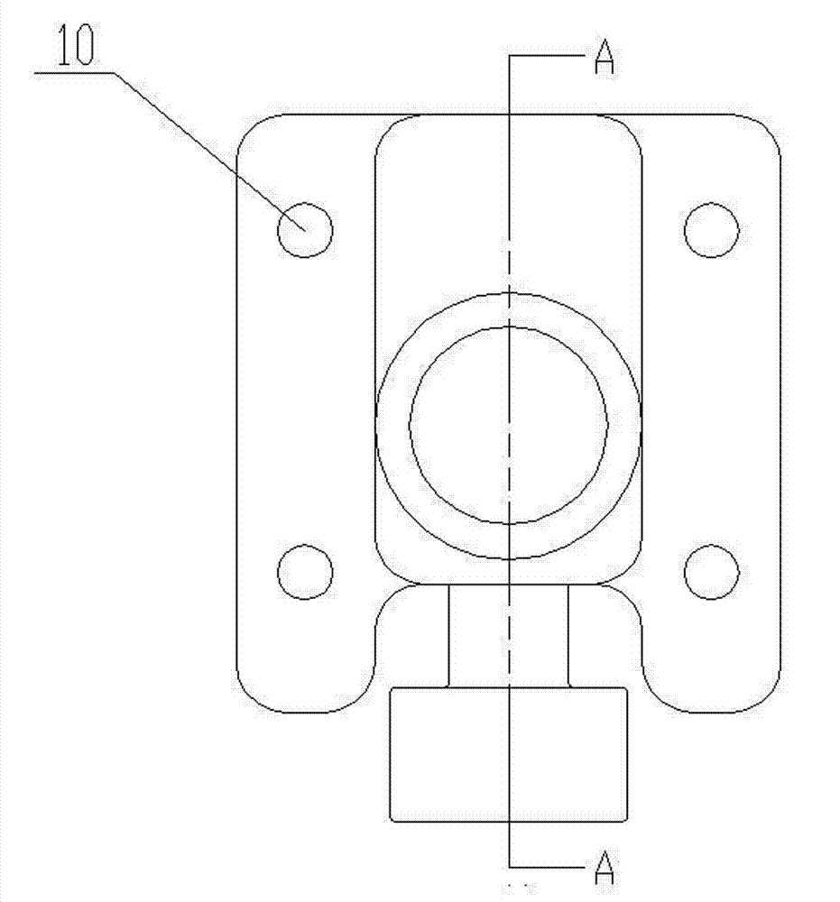
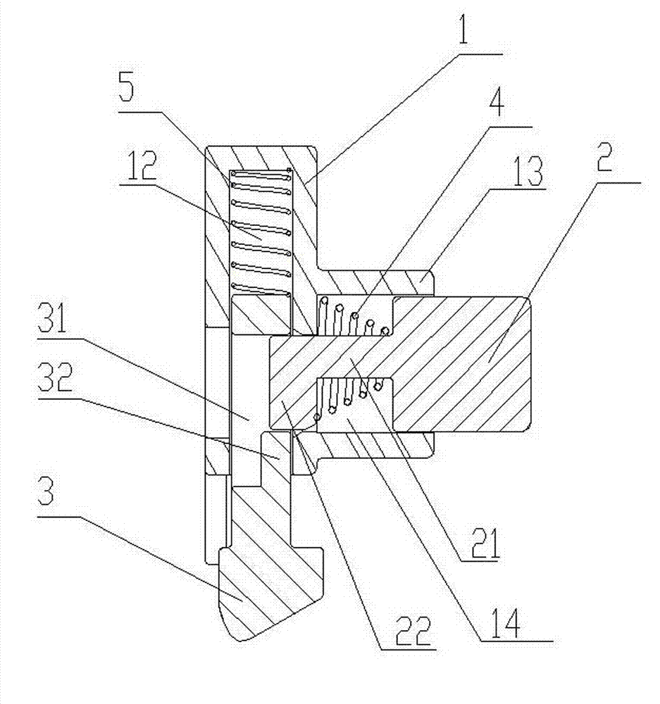
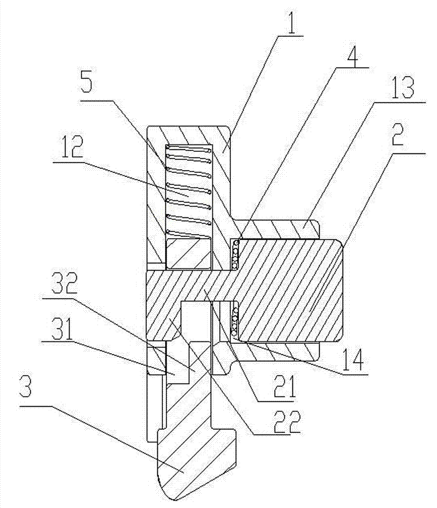
[0021] An example of a mechanical button lock Figure 1-5 Shown, the specific implementation manner of this embodiment is described in detail below in conjunction with accompanying drawing:

[0022] The invention provides a mechanical button lock with a high degree of automation for automatic replacement of the battery box of an electric vehicle, comprising a lock body 1, a lock tongue channel 12 guiding the lock tongue along the up and down direction inside the lock body 1, and a lock tongue channel 12 12 is that one end is provided with an opening for the deadbolt 3 to be loaded into, and the other end is an unopened blind end. The lock body 1 is provided with a lock cylinder passage 14 which is vertically communicated with the deadbolt passage 12 around the deadbolt passage 12. Core channel 14 is the hole in the boss 13 that lock body 1 side is provided with, and lock core 2 is loaded into lock body through the opening that lock core channel 14 offers on lock body side, and...


PUM


Abstract

The invention relates to a mechanical button lock. The mechanical button lock comprises a lock body and a spring bolt and a lock cylinder which are arranged in the lock body; the spring bolt does reciprocating motion relative to the lock body and has a locking position that the spring bolt is extended out of the lock body and an unlocking position that the spring bolt is retracted into the lock body; the movement direction of the lock cylinder is perpendicular to that of the spring bolt, and the lock cylinder has an avoiding position and a locking and stopping position; when the lock cylinder is positioned at the locking and stopping position, the spring bolt is locked at the locking position by combination of the lock cylinder and a locking and stopping structure which is correspondingly arranged on the spring bolt; when the lock cylinder is positioned at the avoiding positioning, the spring bolt moves freely by avoiding of the lock cylinder and the locking and stopping structure which is correspondingly arranged on the spring bolt; a spring bolt spring which is used for applying acting force to the spring bolt to ensure that the spring bolt moves toward the locking position, and a lock cylinder spring which is used for applying action force to the lock cylinder to ensure that the lock cylinder moves toward the locking and stopping position are arranged in the lock body; and one end of the spring bolt, which is extended out of the lock body when the spring bolt is positioned at the locking position, is provided with an inclined surface which is pushed by a corresponding object which moves in a direction perpendicular to the movement direction of the spring bolt into the lock body. According to the mechanical button lock, a battery box of an electric vehicle is automatically replaced by a pure mechanical mode.

Description

technical field [0001] The invention relates to a locking device for a battery box of an electric vehicle, in particular to a mechanical button lock. Background technique [0002] At present, in the automatic battery replacement device of the electric vehicle charging station of the State Grid, the electrical control is generally used to realize the unlocking / unlocking state of the battery compartment. Due to the short life of the electrical control, it is difficult to maintain, the cost is high, and the stability of the core control program is also low. There are certain hidden dangers. Compared with the shortcomings of electrical control instability, it is a relatively simple and reliable way to achieve locking with a mechanical structure. [0003] In the prior art, mechanical locks are generally used to realize the locking and opening of the corresponding devices. For example, the Chinese patent "button-type sliding window lock" with the publication number CN 2095913U dis...

Claims


Application Information

Patent Timeline
Patent Type & Authority Applications(China)
IPC IPC(8): E05C19/00
Inventor 胡新举郝战铎丁习坤宋兵兵李红勋张铁军郑淑利谢梦雪李国杰刘辉勇王鹏光王浩赵军涛谢峰涛王慧杰
Owner XJ ELECTRIC
Learn More