
Pilot-operated electromagnetic directional valve

An electromagnetic reversing valve and pilot-operated technology, applied in valve details, multi-way valves, valve devices, etc., can solve problems such as easy scratches on screws, facilitate disassembly and maintenance, enhance sealing reliability, and improve assembly pass rate Effect

Inactive Publication Date: 2013-01-16
JINAN FUCHI TECH CO LTD
View PDF7 Cites 11 Cited by
  • Summary
  • Abstract
  • Description
  • Claims
  • Application Information

AI Technical Summary

Problems solved by technology

[0003] The technical problem solved by the invention is to provide a pilot-operated electromagnetic reversing valve, which has good sealing performance, solves the problem that the screw is easy to scratch the "O" ring during the assembly process, and improves the reliability of the seal of the manual adjustment rod

Method used


Image

  • Pilot-operated electromagnetic directional valve
  • Pilot-operated electromagnetic directional valve

Examples


Embodiment Construction

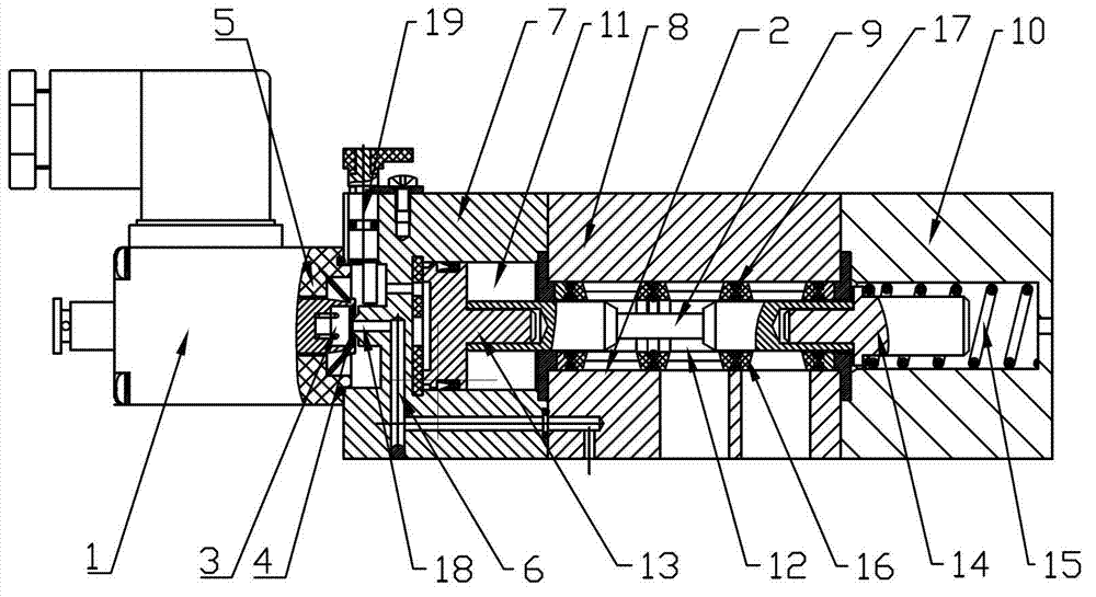
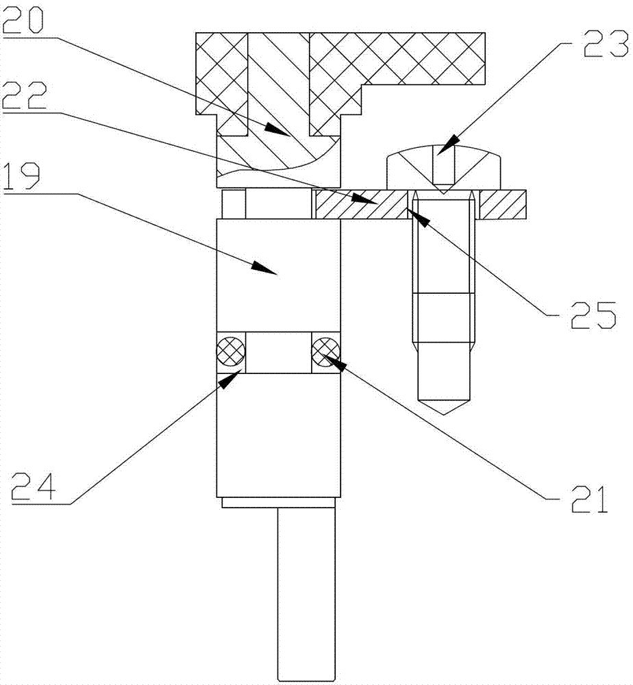
[0013] Such as Figure 1-2 As shown, the pilot electromagnetic reversing valve of the present invention includes an electromagnetic pilot valve 1, an air path control main valve 2 and a manual adjustment rod assembly 19, and the air path control main valve 2 includes a control end cover 7, a valve body 8 and The reset end cover 10, the control end cover 7, the valve body 8 and the reset end cover 10 are connected in sequence, the other end of the control end cover 7 is connected with the electromagnetic pilot valve 1, and the manual adjustment rod assembly 19 is set On the control end cover 7, the manual adjustment rod assembly 19 includes a manual adjustment rod 20, an "O" ring 21, a positioning plate 11, and a positioning screw 23, and the manual adjustment rod 20 extends into the part inside the control end cover 7 An annular groove 24 is provided, and the "O" ring 21 is placed in the annular groove 24. The end of the manual adjustment rod 20 protruding from the control end...


PUM


Abstract

The invention discloses a pilot-operated electromagnetic directional valve which comprises electromagnetic pilot-operated valve, a gas circuit control master-valve and a manual regulating rod component. The gas circuit control master-valve comprises a control end cover, a valve body and a return end cover. The manual regulating rod component is disposed on the control end cover and comprises a manual regulating rod, an 'O'-shaped ring, a positioning plate and a positioning screw. An extension of the manual regulating rod, inside the control end cover, is provided with a circular groove, and the 'O'-shaped ring is disposed in the circular groove. Another extension of the manual regulating rod, outside the control end cover, is also provided with a circular groove, and one end of the positioning plate is clamped to the circular groove at the end of the manual regulating rod. One end of the positioning plate, extending out of the circular groove, is provided with a screw hole, and the positioning screw penetrates through the screw hole on the positioning plate to fasten the positioning plate onto the control end cover. A seal combined ring is disposed on a valve stem inside the valve body and is a bidirectional seal combined ring resistant to low temperature. The problem that the existing design is poor in airtightness is solved, sealing reliability is enhanced, and gas leakage is reduced effectively.

Description

technical field [0001] The invention relates to a pilot electromagnetic reversing valve, in particular to a two-position three-way pilot electromagnetic reversing valve. Background technique [0002] At present, the sealing effect of the existing pilot-operated electromagnetic reversing valve is not very good, and the sealing reliability is relatively poor. The inner combination ring of the spacer mostly adopts a one-way sealing combination ring. The disadvantage of the one-way sealing combination ring is that the sealing effect is not very good. , may cause air leakage and affect the normal operation of the pilot electromagnetic reversing valve. At the same time, the "O" ring assembled on the manual adjustment rod of the pilot electromagnetic reversing valve in the existing design must pass through a positioning threaded hole. After the manual adjustment rod is positioned, the positioning screw is then screwed in. During the assembly process, The screw is easy to scratch t...

Claims


Application Information

Patent Timeline
Patent Type & Authority Applications(China)
IPC IPC(8): F16K11/07F16K31/14F16K31/06
Inventor 张峰孙果
Owner JINAN FUCHI TECH CO LTD
Learn More