Device and method for measuring non-contact gaps

A non-contact, measurement method technology, applied in the direction of measuring devices, optical devices, instruments, etc., can solve problems such as inability to obtain point data, high output impedance, and unstable operation of instruments

Inactive Publication Date: 2013-01-16
ZHEJIANG UNIV
View PDF5 Cites 6 Cited by
  • Summary
  • Abstract
  • Description
  • Claims
  • Application Information

AI Technical Summary

Problems solved by technology

[0006] (2) The contact gap measurement method is easy to cause wear and damage to the product surface, and the reproducibility is not high
However, its output impedance is high and its load capacity is poor; the influence of

Method used


Image

  • Device and method for measuring non-contact gaps
  • Device and method for measuring non-contact gaps
  • Device and method for measuring non-contact gaps

Examples


Embodiment Construction

[0057] The present invention will be further described below in conjunction with the accompanying drawings and embodiments.

[0058] Such as Figure 1-Figure 4 As shown, the present invention includes

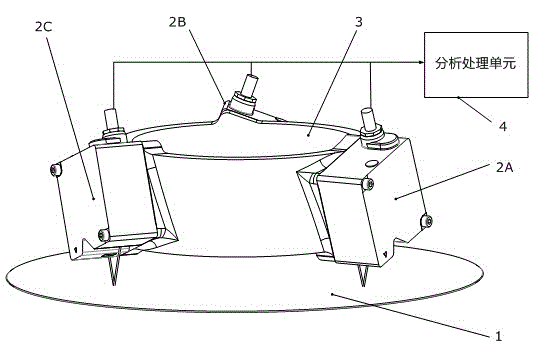
[0059] 1. A non-contact gap measuring device, characterized in that it includes at least three non-contact displacement sensors 2 and an analysis and processing unit 4;

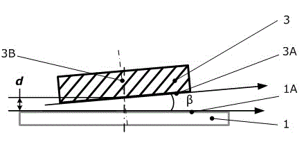
[0060] Three non-contact displacement sensors 2 are respectively installed on the upper measured object 3 in the form of three non-collinear points, and their non-contact measurement directions are all perpendicular to the lower surface 3A of the upper measured object. The three non-contact displacement sensors 2 The measurement zero point of the upper part coincides with the lower surface 3A of the upper part of the measured object, and the lower surface 3A of the upper part of the measured object is parallel or has an angle with respect to the upper surface 1A of the lower part of the measured object.

[0...


PUM


Abstract

The invention discloses a device and a method for measuring non-contact gaps. The method is used for measuring the three degrees of freedom of a gap formed between the lower surface of an upper measured object and the upper surface of a lower measured object. Measuring sensors are mounted on the upper measured object in a non-collinear three-point manner, measuring directions of the measuring sensors are perpendicular to the lower surface of the upper measured object, and zero positions of the measuring sensors are adjusted to coincide with the lower surface of the upper measured object. Three distances between laser emitting points on the lower surface of the upper measured object and corresponding laser reflecting points on the upper surface of the lower measured object are measured, and the three degrees of freedom between the lower surface of the upper measured object and the upper surface of the lower measured object can be obtained via algorithm processing. The method can be used for pose position measurement and regulation of an immersion unit mounted on a movement platform in immersed photoetching, can also be used for measuring pose position in a three-dimensional space, and is especially applicable to precise measurement for narrow gaps.

Description

technical field [0001] The invention relates to a geometric quantity measuring device and method, in particular to a non-contact gap measuring device and method. Background technique [0002] Small gaps are common in the lithography industry, but are very important, such as: the liquid gap between the immersion cell and the silicon wafer in immersion lithography; the liquid gap between the mask and the silicon wafer in imprint lithography. gas gap. Such gaps are usually formed by the lower surface of the upper measured object and the upper surface of the silicon wafer, which have non-circumferential symmetry. The quality of these gaps is closely related to the quality of the exposure pattern. When the immersion lithography equipment performs exposure, the immersion unit will be installed above the silicon wafer, and maintain the immersion flow field during the scanning process of the silicon wafer driven by the wafer holder. In order to ensure the exposure quality, it is ...

Claims


Application Information

Patent Timeline
IPC IPC(8): G01B11/03G01B11/26
Inventor 傅新邵杰杰陈文昱施丽青
Owner ZHEJIANG UNIV
Why Eureka
Try Eureka