Eureka AIR delivers breakthrough ideas for toughest innovation challenges, trusted by R&D personnel around the world.

Method for estimating position of branching joint of transformer in transformer substation

A transformer tap, transformer technology, applied in the direction of instruments, measuring electricity, measuring devices, etc., can solve the practical constraints of the application, cannot fundamentally solve the problem of the accuracy of the basic data of the dispatching center, and reduce the power grid operators' awareness of the power grid operating status. issues of judgment and control

Active Publication Date: 2013-01-16
CHINA ELECTRIC POWER RES INST +1
View PDF5 Cites 11 Cited by
  • Summary
  • Abstract
  • Description
  • Claims
  • Application Information

AI Technical Summary

Problems solved by technology

The right or wrong position of the transformer tap has a great impact on the state estimation results, and the impact on subsequent applications such as power flow analysis, voltage stability analysis, and AVC cannot be ignored. In severe cases, the calculation results will be unavailable or unreliable. This restricts the practical application of these applications, thereby reducing the ability of grid operators to judge and control the grid operating status
[0003] Due to the congenital deficiency of dispatch center information, the accuracy of the basic data of the dispatch center cannot be fundamentally solved through the improvement of the state estimation model and algorithm of the dispatch center

Method used


Image

  • Method for estimating position of branching joint of transformer in transformer substation
  • Method for estimating position of branching joint of transformer in transformer substation
  • Method for estimating position of branching joint of transformer in transformer substation

Examples


Embodiment 1

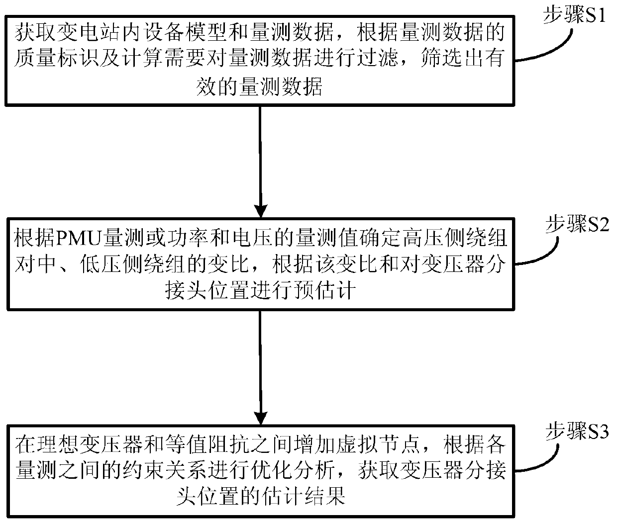
[0035] The present invention provides a first embodiment of a method for estimating the position of a transformer tap in a substation, the specific process of which is as follows figure 1 shown, including:

[0036] In step S1, the equipment model and measurement data in the substation are obtained, and the measurement data is filtered according to the quality identification of the measurement data and calculation needs, and effective measurement data is screened out.

[0037] Among them, the acquired measurement data includes nameplate parameters of the transformer, power, voltage, current measurement and PMU measurement of each equipment.

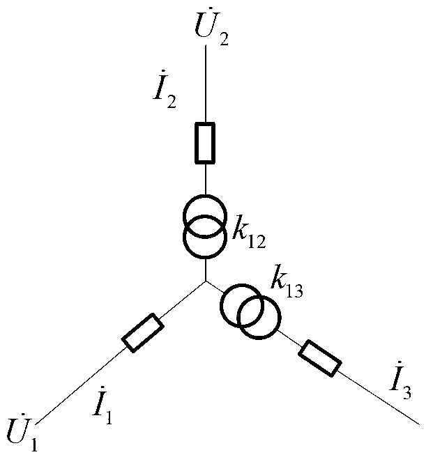
[0038] Step S2, determine the transformation ratio k of the high-voltage side winding to the middle and low-voltage side windings according to the PMU measurement or the measurement value of power and voltage 12 and k 13 , according to the transformation ratio k 12 and k 13 Pre-estimation of transformer tap locations.

[0039] In step...

Embodiment 2

[0041] Embodiment 2 of a method for estimating the position of a transformer tap in a substation provided by the present invention, wherein:

[0042] The quality identification of the measurement data in step S1 includes measurement normal and data jump or no change, etc., judge whether the measurement data is reliable according to the quality indicators such as measurement normal and data jump or no change, and calculate the required and reliable The measurement data is filtered out as valid measurement data.

[0043] In step S2, if there are PMU measurements on each side of the transformer, the transformation ratio k of the high-voltage side windings to the medium and low-voltage side windings is determined according to the PMU measurements 12 : If there is no PMU measurement on each side of the transformer or the PMU measurement is incomplete, determine the transformation ratio k of the high-voltage side winding to the medium and low-voltage side windings according to the...

Embodiment 3

[0061] Embodiment 3 of a method for estimating the position of a transformer tap in a substation provided by the present invention, its calculation flow chart and method flow chart are as follows Figure 5 with Image 6 shown, including:

[0062] Step S1′, obtain the equipment model and measurement data in the substation, filter the measurement data according to the quality identification and calculation needs of the measurement data, and filter out effective measurement data, wherein the obtained measurement data includes the nameplate of the transformer Parameters, power, voltage, current measurement and PMU measurement of each device.

[0063] Step S201, according to the PMU measurement or the power and voltage measurement values, respectively calculate the transformation ratio k of the three-phase high-voltage side windings of the transformer to the medium and low-voltage side windings 12 and k 13 , judging the transformation ratio k obtained from the three-phase 12 an...


PUM


Abstract

The invention provides a method for estimating a position of a branching joint of a transformer in a transformer substation. The method comprises the following steps of: 1, acquiring an equipment model in the transformer substation and measurement data, filtering the measurement data according to a mass identifier and a calculation demand of the measurement data, and selecting effective measurement data, wherein the acquired measurement data comprise a name plate parameter of the transformer and power, voltage and current measurement and pulse modulation unit (PMU) measurement of each set of equipment; 2, determining transformation ratios k12 and k13 of a high-voltage side winding to a medium-voltage side winding and a low-voltage side winding according to the PMU measurement or a power measurement value and a voltage measurement value, and pre-estimating the position of the branching joint of the transformer according to the transformation ratios k12 and k13; and 3, adding a virtual node between an ideal transformer and equalized impedance, performing optimization analysis according to a constriction relation between the measurements, and acquiring an estimation result of the position of the branching joint of the transformer. The position of the branching joint of the transformer is calculated and estimated by using various original parameters and data in the transformer substation, and the estimation result is accurate and real-time.

Description

technical field [0001] The invention relates to the field of power system calculation, in particular to a method for estimating the position of a transformer tap in a substation. Background technique [0002] With the development of the power grid and the improvement of the management level of the power grid, the scope of business involved in the operation and dispatch of the power system is continuously expanding, and the business volume is also increasing. The modern dispatching center is no longer a simple power grid operation monitoring center. It is not only responsible for safety and operation, but also responsible for transactions and operations. A modernized and automated command and decision-making center. On the other hand, with the improvement of intelligence and comprehensive level of the dispatch center, the dependence on the basic data has also reached an unprecedented level. In fact, with the online operation of various advanced applications, each dispatch c...

Claims


Application Information

Patent Timeline
IPC IPC(8): G01R31/02
Inventor 石飞姜玉磊刘俊姚建国杨胜春杨争林於益军冯树海李峰王勇汤必强郭晓蕊徐鹏潘玲玲
Owner CHINA ELECTRIC POWER RES INST
Why Eureka
Eureka Blog
Learn More