Infrared touch screen receiving structure

A technology of infrared touch screen and receiving structure, applied in the direction of instrument, electrical digital data processing, input/output process of data processing, etc., can solve the problems of rising cost and volume, small volume, complicated maintenance, etc. rate, the effect of preventing the generation of false signals

Active Publication Date: 2013-01-16
TOP TOUCH ELECTRONICS
View PDF4 Cites 5 Cited by
  • Summary
  • Abstract
  • Description
  • Claims
  • Application Information

AI Technical Summary

Problems solved by technology

Touch screens using acoustics and other materials technology have their insurmountable barriers, such as damage and aging of a single sensor, fear of contamination of the touch interface, destructive use, and complicated maintenance, etc.
[0005] Since the performance of infrared touch screen mainly depends on the quality and quantity of infrared emitting tubes and infrared receiving tubes, each infrared touch screen is equipped with a considerable number of infrared emitting tubes and infrared receiving tubes, too many infrared emitting tubes and infrared receiving tubes will cause The double increase of cost and volume, especially because the infrared receiving tube is a single independent processing unit and its volume is small, the precision requirement is particularly high when manufacturing

Method used


Image

  • Infrared touch screen receiving structure
  • Infrared touch screen receiving structure
  • Infrared touch screen receiving structure

Examples


Embodiment 1

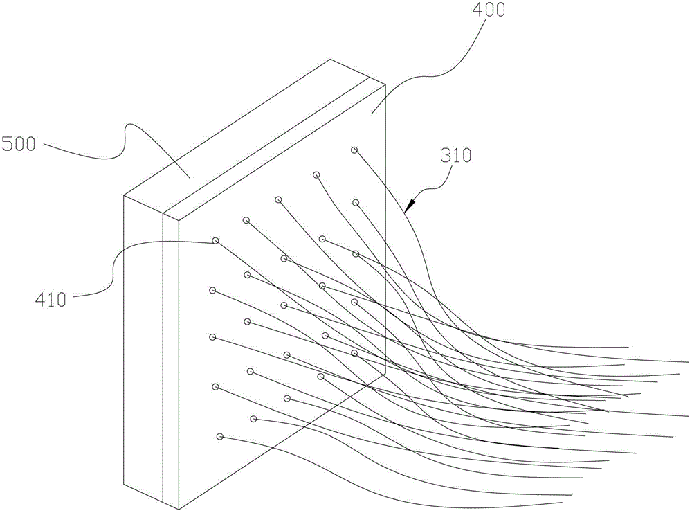
[0050] Such as figure 1 , figure 2 with Figure 5As shown, the infrared touch screen receiving structure includes an infrared receiving terminal 300, an optical fiber 310, an infrared imaging device 500, and an image processing module (not shown in the figure), wherein the infrared receiving terminal 300 is used to fix the optical fiber 310 for receiving infrared signals; To receive the infrared signal sent by the infrared transmitting device, the infrared receiving terminal 300 is provided with an optical fiber installation hole (not shown in the figure), and one end of the optical fiber 310 is fixedly installed in the optical fiber installation hole; the infrared imaging device 500 is used to receive the infrared signal transmitted by the optical fiber 310 And form corresponding pixel points according to the infrared signal; the image processing module is electrically connected with the infrared imaging device 500, and is used to convert the pixel points of the infrared im...

Embodiment 2

[0056] Such as figure 1 , image 3 with Figure 5 As shown, the second embodiment differs from the first embodiment only in the structure of the infrared emitting device, while the receiving structure of the infrared touch screen is the same, which will not be repeated here.

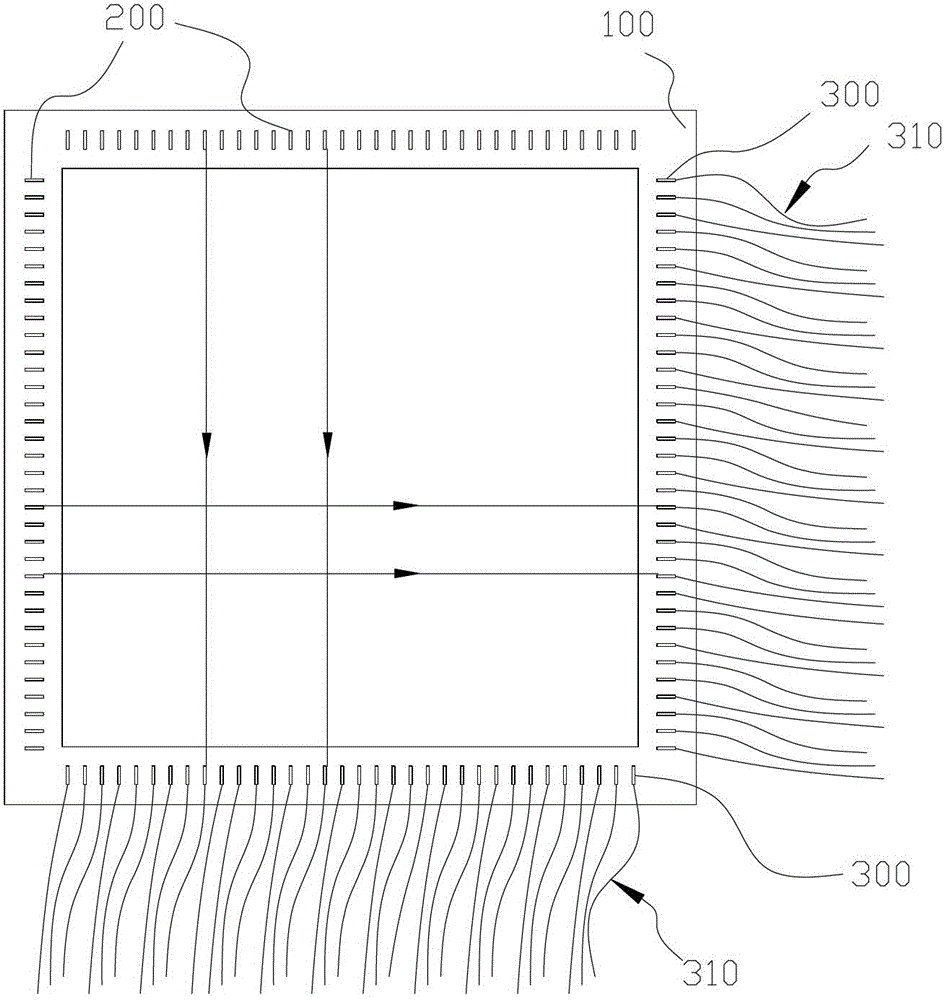
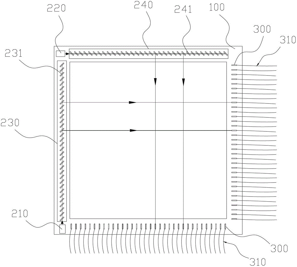
[0057] In this embodiment, the infrared emitting device includes a rectangular circuit board frame 100, two infrared emitting tubes (that is, the first infrared emitting tube 210 and the second infrared emitting tube 220), two light-transmitting mirror groups (that is, the first light-transmitting mirror group 230 and the second light-transmitting mirror group 240). Wherein the rectangular circuit board outer frame 100 is used to form the infrared signal of criss-cross pattern, and this rectangular circuit board outer frame 100 is arranged on the front side of infrared touch screen; The ends of the adjacent two sides of the frame 100; the two light-transmitting mirror groups correspond to the two infr...

Embodiment 3

[0062] Such as figure 1 , Figure 4 with Figure 5 As shown, the third embodiment is different from the first embodiment only in the structure of the infrared emitting device, while the structure of the infrared touch screen receiving is the same, and will not be repeated here.

[0063] In this embodiment, the infrared emitting device includes a rectangular circuit board frame 100 , an infrared emitting tube 250 , a first light-transmitting mirror group 260 , and a second light-transmitting mirror group 270 . Among them: the rectangular circuit board outer frame 100 is used to form criss-cross infrared signals, and the rectangular circuit board outer frame is arranged on the front side of the infrared touch screen; the infrared emitting tube 250 is used to emit infrared signals, and the infrared emitting tube 250 is arranged on the rectangular circuit The end portion of one side of the board outer frame 100; the first light-transmitting mirror group 260 is used to transmit a...


PUM


Abstract

The invention discloses an infrared touch screen receiving structure which comprises infrared receiving terminals, optical fibers, an infrared imaging device and an image processing module, wherein the infrared receiving terminals are used for fixing the optical fibers for receiving infrared ray signals; the optical fibers are used for receiving the infrared ray signals sent by an infrared sending device, and one end of each optical fiber is fixedly mounted on the corresponding infrared receiving terminal; the infrared imaging device is used for receiving the infrared ray signals transmitted by the optical fibers and forming corresponding pixel points according to the infrared ray signals; and the image processing module is electrically connected with the infrared imaging device and used for converting the pixel points to coordinate information of an infrared touch screen touch area. The infrared touch screen receiving structure is capable of realizing functions of infrared receiving tubes of a common infrared touch screen by the aid of one infrared imaging device, and manufacture cost can be effectively lowered as the optical fibers and the infrared imaging device are low in cost. Besides, the optical fibers are much smaller than the common infrared receiving tubes and beneficial to resolution enhancement of an infrared touch screen.

Description

[0001] technical field [0002] The invention relates to an infrared touch screen technology, in particular to an infrared touch screen receiving structure. [0003] Background technique [0004] The infrared touch display screen uses the dense infrared signal matrix in the X and Y directions to detect and locate the user's touch. The infrared touch screen installs a circuit board frame in front of its display, and the circuit board arranges infrared emitting tubes and infrared receiving tubes on the four sides of the screen, forming a horizontal and vertical crossing infrared signal matrix one by one. When the user touches the screen, the finger will block the two horizontal and vertical infrared signals passing through the position, so the position of the touch point on the screen can be judged. Any touching object can change the infrared signal on the contact point to realize the touch screen operation. Infrared touch screens are not affected by current, voltage and st...

Claims


Application Information

Patent Timeline
Patent Type & Authority Applications(China)
IPC IPC(8): G06F3/042
Inventor 毛肖林
Owner TOP TOUCH ELECTRONICS
Why Eureka
Try Eureka