Network minimum path set determination method based on adjacency list

A technique for determining methods and adjacency lists, applied in special data processing applications, instruments, electrical digital data processing, etc., to achieve wide application prospects, high efficiency, and simple methods

Inactive Publication Date: 2013-01-16
中国兵器科学研究院
View PDF4 Cites 15 Cited by
  • Summary
  • Abstract
  • Description
  • Claims
  • Application Information

AI Technical Summary

Problems solved by technology

[0004] The purpose of the present invention is to provide a method for determining the minimum path set suitable for large-scale complex network systems, to solve the design simulation and performance evaluation problems of large-scale complex network systems, mainly including 2 steps:

Method used


Image

  • Network minimum path set determination method based on adjacency list
  • Network minimum path set determination method based on adjacency list
  • Network minimum path set determination method based on adjacency list

Examples


Embodiment Construction

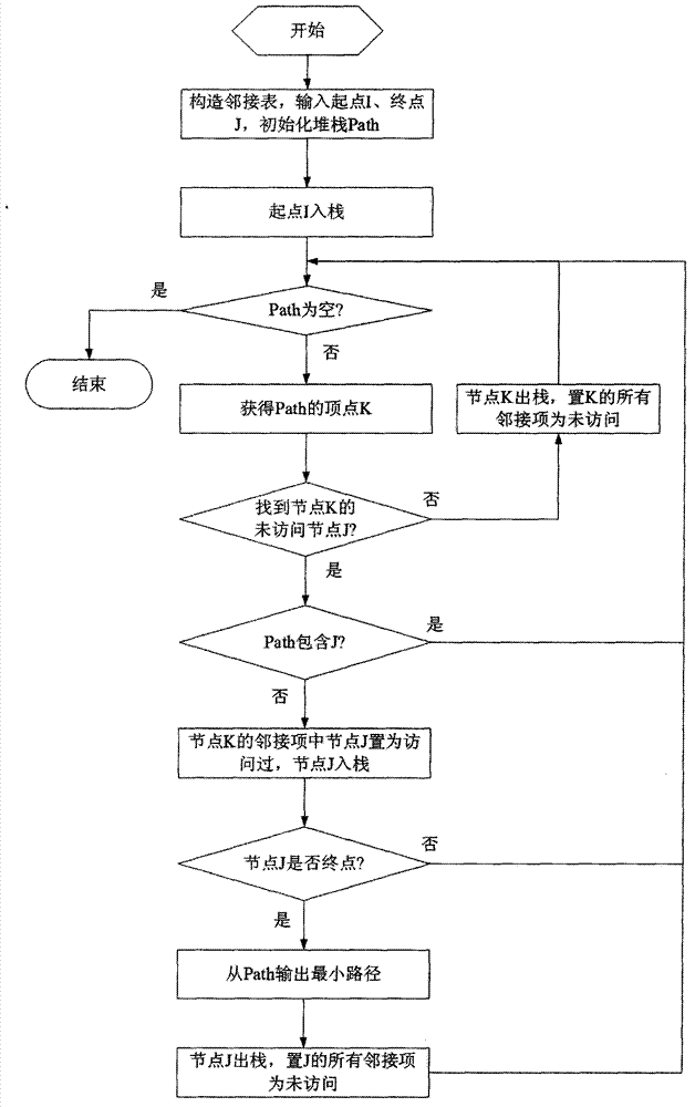
[0011] The flow chart of the present invention is as image 3 shown, including the following steps:

[0012] 1 Construct a new type of adjacency list according to the topology of the network.

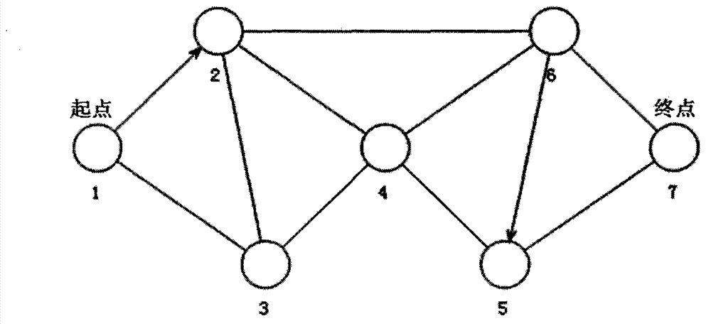
[0013] The adjacency list is a chained storage structure, each row is composed of a node and an adjacency item, and the adjacency item is composed of a node that the node can reach and whether the node has been visited. by figure 1 The shown network is taken as an example, and its adjacency table is shown in Table 1. The i-th row in the table represents the nodes that the i-th node can reach. For example, row 5 represents that node 5 can reach nodes 4 and 7. Since node 6 to node 5 is a directed link, node 6 is not in the adjacency of node 5.

[0014] Another data item in the adjacent item is used to record whether the node has been visited, expressed by visited, visited=0 means not visited, visited=1 means visited. By default the visited attribute of all neighbors is 0.

[0015] T...


PUM


Abstract

The invention provides a network minimum path set determination method based on an adjacency list and aims to solve the problems about design simulation and performance evaluation of a large complex network system. The method mainly comprises the following two steps of: establishing a novel adjacency list according to a topological structure of a network; and traversing the adjacency list by using a depth-first search and backtracking combination method to determine all minimum paths. Nodes and links are not quantitatively restricted. The network minimum path set determination method based on the adjacency list is applicable to a directed network, an undirected network and a mixed network and has a wide application prospect in the large complex network systems such as power, communication, traffic, computers and municipal pipe networks.

Description

technical field [0001] The invention relates to a method for determining the minimum path set of a network system, which belongs to the field of network system design and simulation. Background technique [0002] A network system can be represented by a graph G, figure 1 It is a graph representing the network, the vertices in the graph represent the nodes in the network, the edges represent the links connecting the nodes in the network, and there are no parallel links between nodes. If all the edges in G are directed, it is called a directed network; if all the edges in G are undirected, it is called an undirected network; if there are both directed and undirected edges in G , called a hybrid network. figure 1 It is a hybrid network. Let the starting point be I and the end point be L. The minimum path refers to the path from the starting point I to the end point L that contains the least number of links, and there are no repeated nodes and links in the minimum path. The ...

Claims


Application Information

Patent Timeline
Patent Type & Authority Applications(China)
IPC IPC(8): G06F17/50
Inventor 钱云鹏姬广振涂宏茂刘勤朱正福
Owner 中国兵器科学研究院
Why Eureka
Try Eureka