Visual tracing scattering analysis method of inhomogeneous medium

An analysis method and non-uniform technology, applied in the field of radar, can solve engineering problems such as inability to work, and achieve the effect of overcoming low efficiency, high efficiency and fast calculation

Inactive Publication Date: 2013-01-16
SHANGHAI INST OF ELECTROMECHANICAL ENG
View PDF0 Cites 12 Cited by
  • Summary
  • Abstract
  • Description
  • Claims
  • Application Information

AI Technical Summary

Problems solved by technology

Some engineering problems simply don't work with current computing power

Method used


Image

  • Visual tracing scattering analysis method of inhomogeneous medium
  • Visual tracing scattering analysis method of inhomogeneous medium
  • Visual tracing scattering analysis method of inhomogeneous medium

Examples


Embodiment Construction

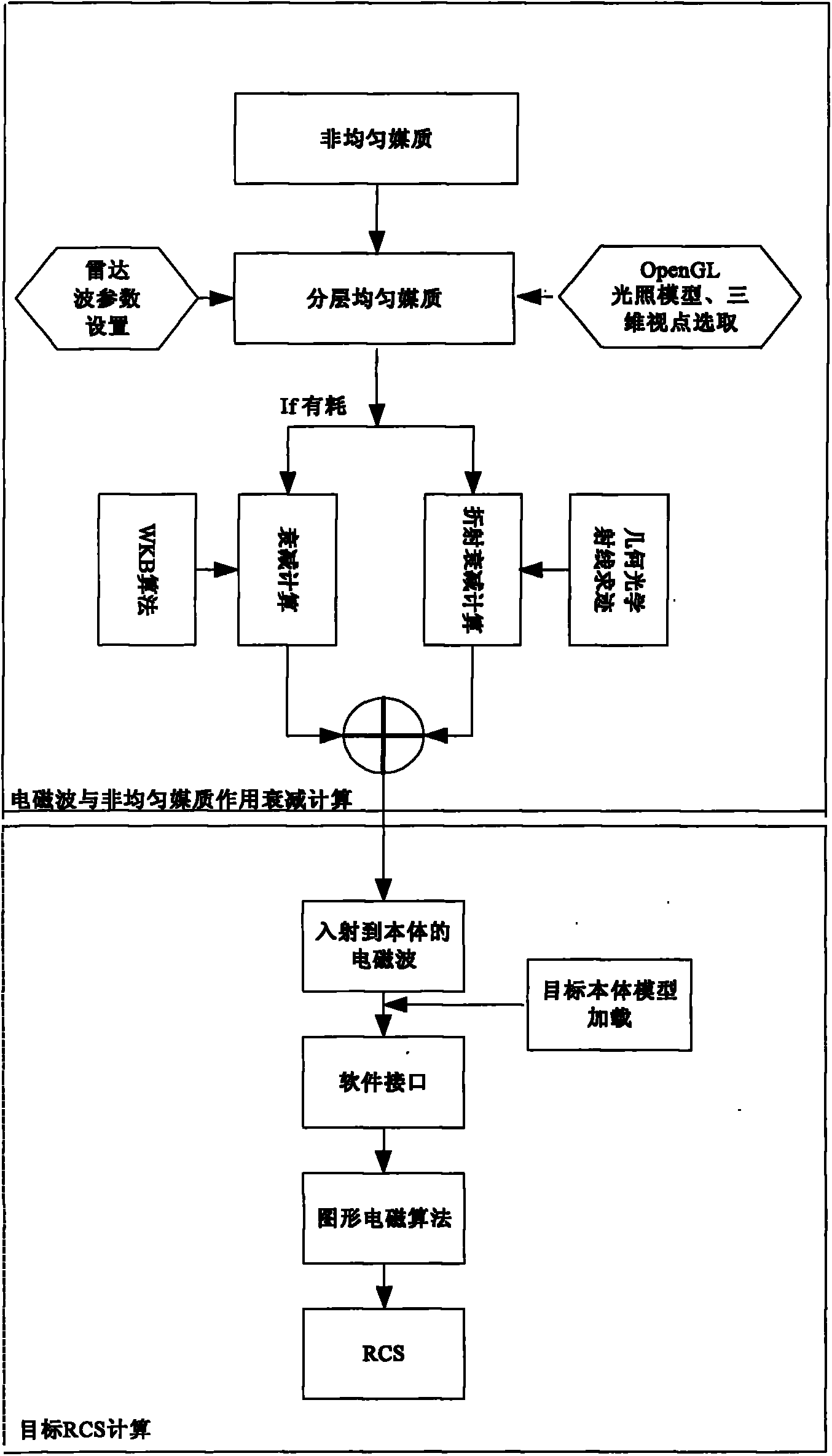
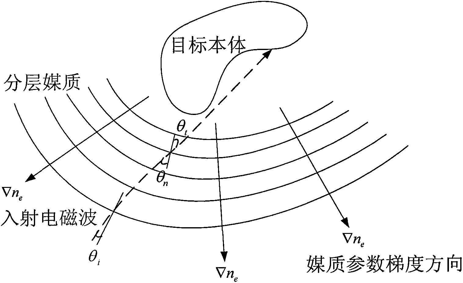
[0016] The present invention will be further described in detail below. see figure 1 Flowchart of the method of visual trace scattering analysis in inhomogeneous media. First, stratify the heterogeneous medium according to its parameter distribution. When the characteristic parameters of the heterogeneous medium are unevenly distributed in the gradient direction, and the medium parameters are approximately uniformly distributed in the vertical direction of the gradient, the accuracy required for the calculation can be calculated Set the characteristic parameter step size, layer the medium area, use the isoparameter surface as the layer boundary, and the area between two adjacent isoparameter surfaces can be equivalent to a uniform medium, and the interface can be any quadratic Surfaces are saved in dxf or mesh format.

[0017] After the radar parameters are determined, in the direction of the radar line of sight, each layered interface is displayed according to the order in ...


PUM


Abstract

The invention discloses an efficient calculation method of a radar scattering cross section of an inhomogeneous medium wrapped target. The method comprises the following steps: firstly equalizing the inhomogeneous medium into a layered homogeneous medium according to electromagnetic parameters; setting up a lighting model and selecting a three-dimensional viewpoint in an OpenGL (open graphics library) and inputting the three parts of information into a graph hardware processor; accomplishing the automatic shielding of a three-dimensional target by using the graph hardware processor; outputting a real-time target image and visible pixel information displayed on a computer screen after the automatic shielding, wherein the visible pixel information includes brightness values (R,G,B) and three-dimensional coordinates (x,y,z) of pixels; displaying medium interfaces at which rays arrive layer by layer in the OpenGL according to the direction of incident electromagnetic waves; extracting the brightness and the coordinate information of the pixels; determining the reflection and refraction of the rays by combination of the electromagnetic parameters at two sides of the interface, so as to trace the direction of the rays and determine the incidence direction of incidence electromagnetic waves of the pixels of the target when the rays arrives at a target body; in a loss medium, synchronously calculating the attenuation of each ray on a transmission journey; and finally, calculating the radar scattering cross section of the inhomogeneous medium wrapped target according to integrals of a physical optical field and a boundary diffraction field. The method has the advantages that a novel method for calculating radar scattering characteristics of the inhomogeneous medium based on graphic display is provided, so that the defects that in a traditional calculation method, a large-sized medium cannot be calculated, and control in manual mode is difficulty are overcome.

Description

technical field [0001] The invention relates to the field of radar technology, in particular to a non-uniform medium visual tracking scattering analysis method, which is mainly applied to the analysis of electromagnetic scattering characteristics of large-scale non-uniform medium-coated targets. Background technique [0002] For the analysis of the electromagnetic properties of inhomogeneous media, most domestic and foreign scholars mainly focus on the scattering characteristics of one-dimensional and two-dimensional plasmas, and the analysis methods used mainly adopt classical analytical methods. In recent years, some scholars have introduced the current more popular The numerical algorithm-FDTD method for scattering simulation of plasma-coated targets, besides few other numerical simulation methods. [0003] FDTD method, as a common method for analyzing time-varying electromagnetic fields at present, has its unique advantages in solving problems such as inhomogeneous media...

Claims


Application Information

Patent Timeline
Patent Type & Authority Applications(China)
IPC IPC(8): G06F19/00
Inventor 王谷黄伟忠杨革文顾村锋胡天俊宋璘琳朱迪陈德红李晨程剑熹
Owner SHANGHAI INST OF ELECTROMECHANICAL ENG
Why Eureka
Try Eureka