
Airborne tubular antenna

An antenna and tubular technology, which is applied in the field of airborne tubular antennas, can solve problems such as antenna breakage, shedding of jackets, and broken wires of wire ropes, and achieve the effects of easy disassembly, improved radiation efficiency, and high reliability

Active Publication Date: 2013-01-16
陕西烽火诺信科技有限公司
View PDF5 Cites 6 Cited by
  • Summary
  • Abstract
  • Description
  • Claims
  • Application Information

AI Technical Summary

Problems solved by technology

[0003] In order to overcome the deficiencies of the above-mentioned prior art, the object of the present invention is to provide an airborne tubular antenna with an operating frequency of 1.6MHz to 30MHz, which solves the problems of the airborne short-wave radio station using antennas such as breakage, shedding of coats, broken wires of wire ropes, and problems caused by resonance. Problems with disturbing harmonics generated

Method used


Image

  • Airborne tubular antenna
  • Airborne tubular antenna

Examples


Embodiment Construction

[0014] The present invention will be further described in detail below in conjunction with the accompanying drawings and specific embodiments.

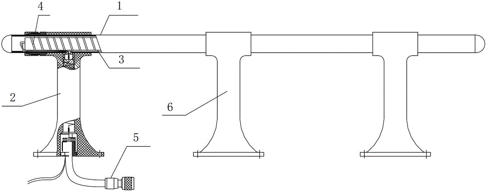
[0015] Such as figure 1 As shown, an airborne tubular antenna of the present invention includes an L-shaped helical radiator 3, the helical radiator 3 is located in the antenna radiation tube 1 and the hollow support frame 2 that are perpendicular to each other, and the hollow support frame 2 is fixed by positioning pins On the antenna radiating tube 1, and the flange faces are on the same side, keep coaxial. The helix 4 on the helical radiator 3 is divided into three sections in the antenna radiation tube 1 . The helix 4 closest to the hollow support frame 2 is the first segment, the next is the second segment, and the farthest is the third segment.

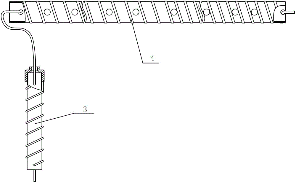
[0016] Such as figure 2 As shown, the pitch of the first helix 4 of the helical radiator 3 is 18mm, the pitch of the second helix 4 is 14mm, the pitch of the third helix 4 is 10mm, ...


PUM

PropertyMeasurementUnit
Pitchaaaaaaaaaa

Abstract

An airborne tubular antenna comprises an L-shaped spiral radiator. The spiral radiator is positioned in an antenna radiant tube and a hollow support frame which are perpendicular to each other, a spiral line on the spiral radiator is divided into three sections in the antenna radiant tube, each section of thread pitch is different, two neighboring sections of spiral lines are hinged, and the spiral line on the spiral radiator is connected with a tail connector of a radio frequency cable. Since a spiral line technology is introduced in the antenna, by the aid of a spiral line model, within a limited structure size of the antenna, length of an antenna radiator can be increased, and radiation efficiency of short-wave communication can be improved. A partial spiral radiator is mounted in the antenna support frame, so that a radiation pattern of the antenna is close to be omnibearing, and the problem of telecommunication of the antenna is solved effectively according to the principle. The antenna has the advantages of convenience in mounting and dismounting, non-maintenance, high reliability and the like.

Description

technical field [0001] The invention belongs to the technical field of antennas, is mainly applied to a helicopter airborne radio station, and relates to an airborne tubular antenna. Background technique [0002] At present, my country's airborne antennas are mostly cable antennas, but the cable antennas have the following disadvantages: the tightness of the cable needs to be adjusted frequently, the cable is prone to wire breakage, the spring fails, the cable jacket cracks and falls off, and the steel wire is damaged by the aircraft. Harmonics generated by resonance caused by vibration affect the normal operation of other airborne equipment and other undesirable phenomena. my country's airborne antenna has been affected by this for a long time, and it has become a long-term criticism of my country's airborne communication system. Contents of the invention [0003] In order to overcome the deficiencies of the above-mentioned prior art, the object of the present invention i...

Claims


Application Information

Patent Timeline
IPC IPC(8): H01Q1/36H01Q1/14
Inventor 张志云卢攀龙拉怀赵艳陈文君沙永胜
Owner 陕西烽火诺信科技有限公司
Learn More