
Multi-phase fault-tolerant permanent magnet synchronous motor disk rotor

A technology of permanent magnet synchronous motor and disc rotor, which is applied to the rotating parts of the magnetic circuit, the shape/style/structure of the magnetic circuit, etc., which can solve the problems of poor suppression of short-circuit current, etc., and achieve easy fixing, low cost and low consumption. The effect of halving

Active Publication Date: 2013-01-16
HARBIN INST OF TECH
View PDF4 Cites 6 Cited by
  • Summary
  • Abstract
  • Description
  • Claims
  • Application Information

AI Technical Summary

Problems solved by technology

[0004] The purpose of the present invention is to solve the problem that the short-circuit current suppression effect of the traditional surface-mounted disc permanent magnet motor is not good, and to provide a multi-phase fault-tolerant permanent magnet synchronous motor disc rotor

Method used


Image

  • Multi-phase fault-tolerant permanent magnet synchronous motor disk rotor
  • Multi-phase fault-tolerant permanent magnet synchronous motor disk rotor
  • Multi-phase fault-tolerant permanent magnet synchronous motor disk rotor

Examples


specific Embodiment approach 1

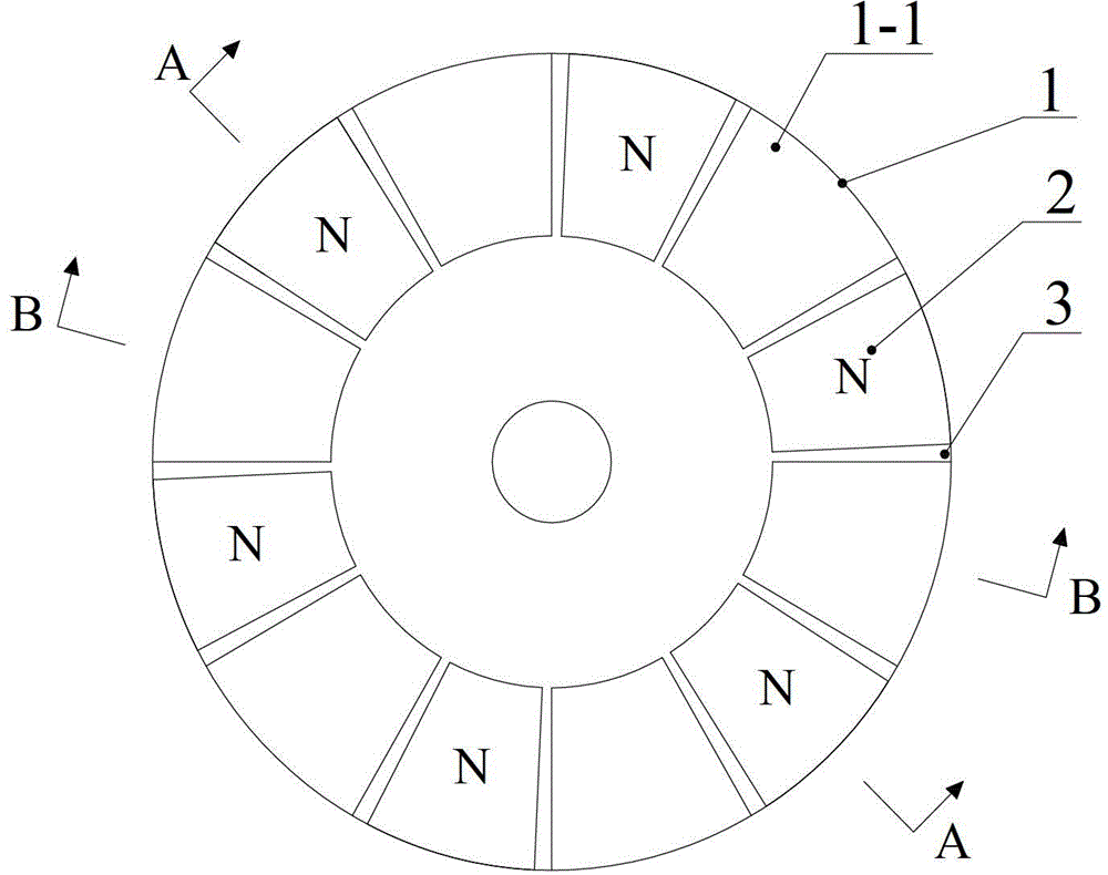
[0014] Specific implementation mode 1: the following combination Figure 1 to Figure 7 Explaining this embodiment, the disc rotor of the multi-tolerant permanent magnet synchronous motor described in this embodiment includes a rotor core 1 and p permanent magnets 2. The rotor core 1 includes a rotor core yoke 1-2 and p rotor core poles 1 -1, the disk surface of the annular rotor core yoke 1-2 is provided with p rotor core poles 1-1, and the p rotor core poles 1-1 are evenly arranged in the circumferential direction, and every two adjacent rotor core poles A permanent magnet slot 3 is formed between 1-1, and each permanent magnet slot 3 is embedded with a permanent magnet 2. The central angle of the sector surface of the permanent magnet 2 is less than or equal to the sector surface central angle of the permanent magnet slot 3. There are p permanent magnets 2 The surface opposite to the stator has the same polarity, and is magnetized in the axial direction, and p is the number o...

specific Embodiment approach 2

[0024] Specific embodiment two: This embodiment will further explain the first embodiment. The rotor core 1 is made of solid steel or laminated with silicon steel sheets.

specific Embodiment approach 3

[0025] Specific embodiment three: This embodiment will further explain the first embodiment. The rotor core 1 is made of amorphous ferromagnetic composite material or SMC soft magnetic composite material.


PUM


Abstract

The invention discloses a multi-phase fault-tolerant permanent magnet synchronous motor disk rotor, belonging to the field of permanent magnet motors. The invention solves the problem that the short-circuit current suppression effect of the traditional surface-mount disk permanent magnet motor is bad. The multi-phase fault-tolerant permanent magnet synchronous motor disk rotor comprises a rotor core and p permanent magnets, wherein the rotor core comprises a rotor core yoke and p rotor core poles; the p rotor core poles are arranged on the disk surface of the annular rotor core yoke; the p rotor core poles are uniformly distributed along the peripheral direction; a permanent magnet slot is formed between every two adjacent rotor core poles; a permanent magnet is embedded into each permanent magnet slot; the central angle of the sector of the permanent magnet is smaller than or equal to the central angle of the sector of the permanent magnet slot; the surfaces of the p permanent magnets opposite to a stator have the same polarity, and axial magnetization is adopted; and p is the pole pair number of the rotor.

Description

Technical field [0001] The invention relates to a disc rotor of a multi-tolerant permanent magnet synchronous motor, belonging to the field of permanent magnet motors. Background technique [0002] With the increasing seriousness of environmental and energy crisis and other issues, society is paying more and more attention to environmental cleanliness and energy security issues, which greatly promotes the development of electric vehicles. For electric vehicles, the reliability and safety of the electric drive system are crucial. In the traditional three-phase permanent magnet synchronous motor, when the winding is open, the winding is short-circuited, and the drive power device is open or short-circuited, the motor's torque output will change drastically, or even fail to work, which will cause damage to the vehicle itself and the personnel in the vehicle. Safety poses a serious threat. Therefore, for safety and reliability considerations, it is extremely important to adopt a mul...

Claims


Application Information

Patent Timeline
Patent Type & Authority Applications(China)
IPC IPC(8): H02K1/27
Inventor 郑萍隋义王鹏飞白金刚吴帆
Owner HARBIN INST OF TECH
Learn More