
Liquid seal anti-vibration device and manufacturing method thereof
An anti-vibration device, liquid technology, applied in the direction of spring/shock absorber manufacturing, shock absorber, shock absorber-spring combination, etc., can solve the problem of flow reduction, internal pressure cannot be fully increased, and vibration reduction cannot be achieved Capability and other issues, to achieve the effect of preventing deformation, reducing vibration, and high vibration damping function
- Summary
- Abstract
- Description
- Claims
- Application Information
AI Technical Summary
Problems solved by technology
Method used
Image

Examples
Embodiment Construction
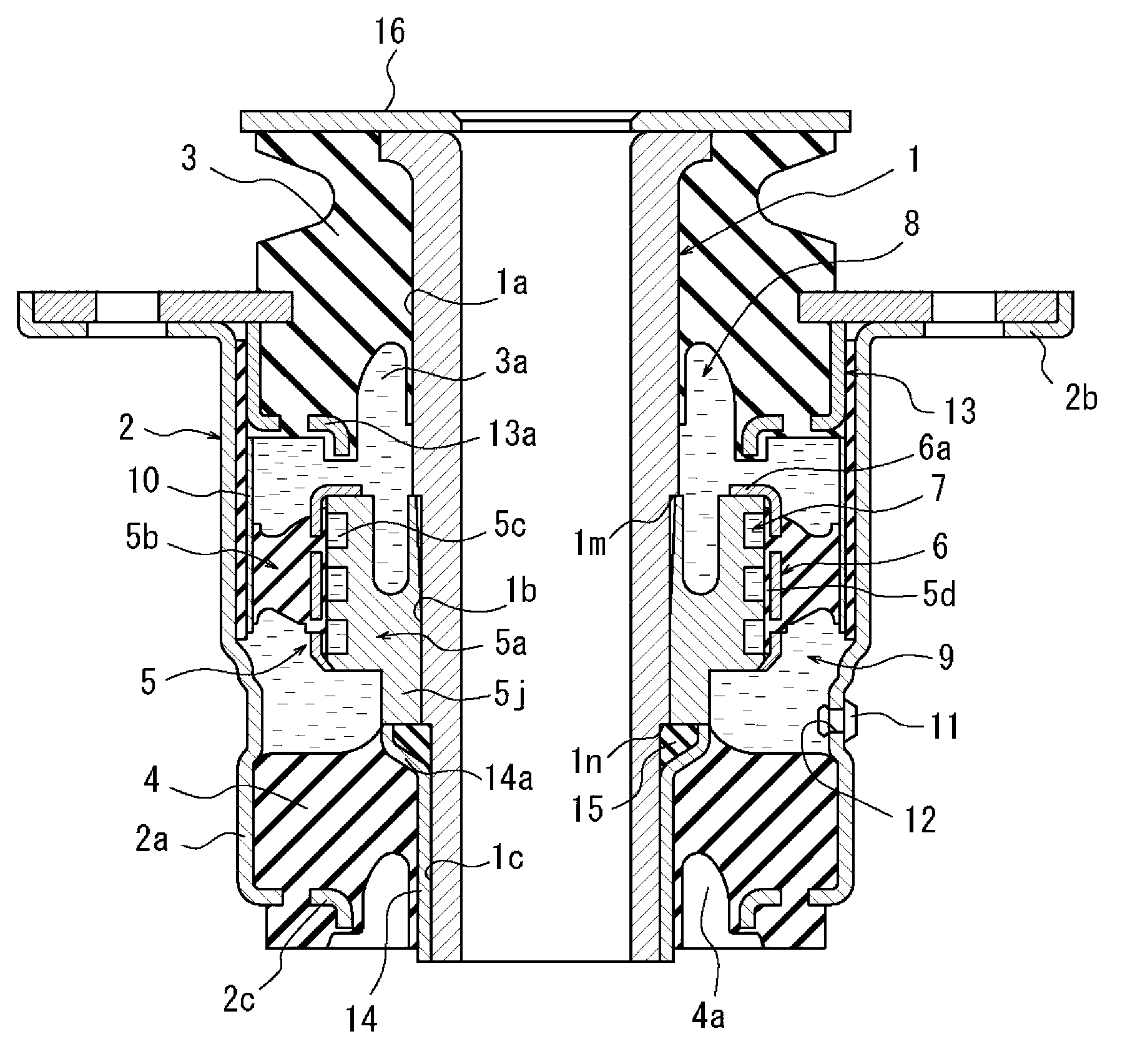
[0074] refer to figure 1 In the embodiment shown, reference numeral 1 designates an inner cylinder provided with a flange at the upper end shown. The inner cylinder 1 may be made of metal and is generally cylindrical. Reference numeral 2 denotes an outer cylinder which is spaced apart from the inner cylinder 1 on the circumferential outside of the inner cylinder 1 and provided with an upper end flange. The outer cylinder 2 is also generally cylindrical and may also be made of metal.
[0075] The inner cylinder 1 and the outer cylinder 2 are connected to each other in a liquid-tight manner by a rubber body 3 at the illustrated upper end and a rubber body 4 at the illustrated lower end. The rubber bodies 3 , 4 are spaced apart from each other in the axial direction of the inner cylinder 1 and the outer cylinder 2 and are arranged between the inner cylinder 1 and the outer cylinder 2 . The space defined by the inner cylinder 1 , the outer cylinder 2 and the rubber bodies 3 , ...
PUM
 Abstract
Description
Claims
Application Information