Punch press mold

A technology of molds and punching machines, applied in the direction of pushing out equipment, etc., can solve problems such as the inconvenience of continuous processing

Inactive Publication Date: 2013-01-23
SUZHOU TANGFENG METAL PROD
View PDF0 Cites 2 Cited by
  • Summary
  • Abstract
  • Description
  • Claims
  • Application Information

AI Technical Summary

Problems solved by technology

[0002] In the existing stamping process, especially when processing thin plates, due to the relatively small gap between the knife edges or the friction between the punch and the product, the workpiece or the generated waste is taken out of the die instead of the material from the lower end of the die. When such a situation occurs during continuous processing, the operator has to stop processing to clean up, which brings great inconvenience to continuous processing

Method used


Image

  • Punch press mold
  • Punch press mold

Examples


Embodiment Construction

[0011] The present invention is described below in conjunction with accompanying drawing.

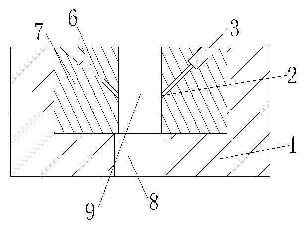
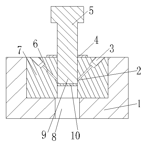
[0012] as attached Figure 1-2 The shown punch mold of the present invention includes a die backing plate 1 and a die 7; the bottom of the die backing plate 1 is provided with a discharge port 8; the die 7 is embedded and installed in the die On the backing plate 1; the die 7 at the upper end of the discharge port 8 is provided with a die hole 9; the die 7 is provided with a threaded connection hole 3 at a certain angle with the axis of the die hole 9; the thread The connection hole 3 is connected to the output port of the peripheral high-pressure air source; the bottom of the threaded connection hole 3 is provided with an air inlet passage 6, and the end air outlet 2 communicates with the die hole 9; when in use, when the punch 5 punches out a qualified When the workpiece 10, as long as the switch that controls the air source to enter the air intake channel on the high-pressure air so...


PUM


Abstract

The invention discloses a punch press mold, comprising a female die base plate and a female die; the bottom of the female die base plate is provided with a discharge port; the female die is embedded in the female die base plate; a female die hole is arranged on the female die of the upper end of the discharge port; a screw connection hole forming a certain angle with an axis of the female die hole is arranged on the female die; the screw connection hole is connected with an external high-pressure air source output port; the bottom of the screw connection hole is connected with an air inlet channel; an air outlet port of the bottom end is communicated with the female die hole; according to the scheme of the punch press mold, a male die after being punched and cut enters the air inlet port so as to blow a molded work piece off from the male die, in this way, the influence on machining speed and quality caused by the fact that the male die takes out the machined and molded work piece in the raising process is avoided.

Description

technical field [0001] The invention relates to a punch die, in particular to a die for preventing a punch from taking out a formed workpiece, and belongs to the technical field of punch die equipment. Background technique [0002] In the existing stamping process, especially when processing thin plates, due to the relatively small gap between the blades or the friction between the punch and the product, the workpiece or the generated waste is taken out of the die instead of the material from the lower end of the die. When such a situation occurs during continuous processing, the operator has to stop processing to clean up, which brings great inconvenience to continuous processing. Contents of the invention [0003] In view of the above-mentioned technical problems, the object of the present invention is to propose a punch die. [0004] The technical solution of the present invention is achieved in this way: a punch mold, including a die backing plate, a die; the bottom o...

Claims


Application Information

Patent Timeline
Patent Type & Authority Applications(China)
IPC IPC(8): B21D28/14B21D45/02
Inventor 唐剑峰
Owner SUZHOU TANGFENG METAL PROD
Why Eureka
Try Eureka