Method for diagnosing a loaded combustion engine in terms of a leakage in a section of the fresh gas section

A fresh gas line, fresh gas technology, applied in the direction of internal combustion piston engine, combustion engine, fluid tightness test, etc., to achieve good diagnostic results

Active Publication Date: 2020-05-29
VOLKSWAGEN AG
View PDF10 Cites 1 Cited by
  • Summary
  • Abstract
  • Description
  • Claims
  • Application Information

AI Technical Summary

Problems solved by technology

But the problem is that many internal combustion engines used to drive motor vehicles often do not operate in the operating state where there is a (high) boost pressure
Furthermore, this method only detects leaks in the charge air section of the fresh gas line

Method used


Image

  • Method for diagnosing a loaded combustion engine in terms of a leakage in a section of the fresh gas section

Examples


Embodiment Construction

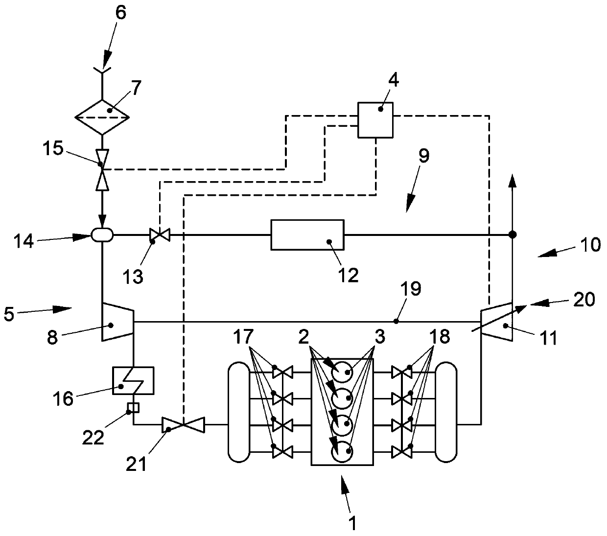
[0026] exist figure 1 The internal combustion engine shown in includes a combustion engine 1 which is constructed with a plurality of cylinders 2 . The cylinder 2 together with a piston 3 guided up and down in the cylinder 2 and a cylinder head (not shown) jointly delimit a combustion chamber in which fresh gas is combusted together with fuel. In this case, the fuel is injected directly into the combustion chamber by (not shown) injectors controlled by the control unit 4 (engine controller). Combustion of the fuel-fresh gas mixture causes piston 3 to move up and down, which in turn is transmitted in a known manner via connecting rods, not shown, to a crankshaft, also not shown, whereby the crankshaft is driven in rotation.

[0027] Fresh gas is fed into the combustion engine 1 via a fresh gas line 5 . For this purpose, air is sucked in from the environment via the intake port 6 , which is then cleaned in an air filter 7 and then fed into a fresh-gas compressor 8 which is par...


PUM


Abstract

A method for diagnosing a combustion machine, wherein the combustion machine comprises at least one internal combustion engine (1) and one intake air line (5) via which fresh air can be fed to the internal combustion engine (1). In addition, at least one intake air compressor (8) and, upstream from the intake air compressor, a control flap (15) are integrated into the intake air line. In one operating state of the combustion machine, the control flap is closed so far that a negative pressure relative to the ambient pressure is produced by means of the running internal combustion engine in theportion of the intake air line that lies between the control flap and the internal combustion engine, with an actual value that is associated with this negative pressure being compared with a target value and the presence or absence of leakage in this portion of the intake air line being deduced from any difference that might exist between the actual value and the target value.

Description

technical field [0001] The invention relates to a method for diagnosing a supercharged internal combustion engine for leaks in a section of a fresh gas line. Background technique [0002] Internal combustion engines used to drive motor vehicles are usually supercharged in order to increase specific power output and reduce specific fuel consumption. The supercharging of internal combustion engines by means of one or more exhaust gas turbochargers is widely used. An exhaust gas turbocharger of this type comprises an exhaust gas turbine with a turbine wheel, which is driven in rotation by the inflow of exhaust gas expelled from the combustion engine of the internal combustion engine. The turbine wheel drives the compressor wheel of the fresh gas compressor via the shaft, which is integrated in the fresh gas line of the combustion engine and by which the fresh gas is compressed. Alternatively, such a fresh gas compressor can also be driven by different drives, for example the ...

Claims


Application Information

Patent Timeline
Patent Type & Authority Applications(China)
IPC IPC(8): F02D41/22F02M26/49F02M26/06F02M35/10
CPCF02D41/22F02M26/49F02M26/06F02M35/10255F02D41/0007F02D2200/0404F02B2039/168F02D23/00F02D9/02F02B37/24F02B33/40F02M35/1038Y02T10/12F02B37/00G01M3/025G01M3/26
Inventor M.豪普沃格尔F.贝尔斯基
Owner VOLKSWAGEN AG
Why Eureka
Try Eureka