Gas-leading sealing structure of gas turbine

A sealing structure and gas turbine technology, which is applied in the direction of gas turbine devices, mechanical equipment, jet propulsion devices, etc., can solve the problems of complex assembly, cumbersome structure, and large amount of calculation, and achieve airflow loss reduction, simple structural design, and simple sealing structure Effect

Active Publication Date: 2013-01-23
HARBIN DONGAN ENGINE GRP
View PDF7 Cites 2 Cited by
  • Summary
  • Abstract
  • Description
  • Claims
  • Application Information

AI Technical Summary

Problems solved by technology

For the design of the bleed air sealing structure of the above-mentioned gas turbine, it is necessary to calculate the bleed air pipeline, the flow resistance of the nozzle, etc., which requires a large amount of calculation, high difficulty, complex assembly, and cu

Method used


Image

  • Gas-leading sealing structure of gas turbine

Examples


Example Embodiment

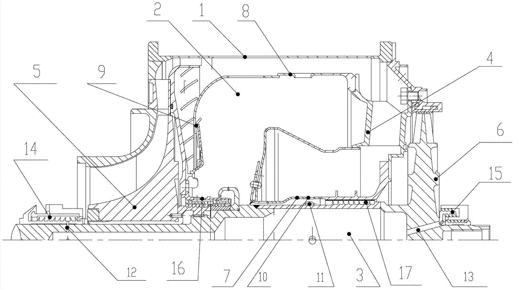
[0007] As shown in the figure, the gas turbine bleed air seal structure includes a casing 1, a flame tube 2, a rotor 3, and a turbine guide hollow blade 4. The rotor 3 is equipped with a compressor rotor 5 and a turbine rotor 6, and the flame The barrel 2 includes an inner wall 7, an outer wall 8, and a front wall 9 and is equipped with turbine guide hollow blades 4. A compressed air channel is provided between the casing 1 and the outer wall 8, and the front wall 9 on the rotor 3. In front of the compressor rotor 5, behind the turbine rotor 6, the front wall 9 and the inner wall 7 are provided with grate seal structures 14, 15, 16, 17, and the inner wall 7 is provided with an air outlet 10, which is located on the rotor 3. The position of the air hole 10 is provided with a tangential hole 11, a vent hole 12 is provided at the grate seal structure 14, and a vent hole 13 is provided at the grate seal structure 15. Both the vent hole 12 and the vent hole 13 pass through the rotor ...


PUM


Abstract

The invention relates to a gas-leading sealing structure of a gas turbine. The gas-leading sealing structure comprises a shell, a flame barrel, a rotor and a turbine guider hollow blade, wherein an air compressor rotor and a turbine rotor are arranged on the rotor; compressed air channels are formed between the shell and the outer wall of the flame barrel as well as between the shell and the front wall of the flame barrel; and comb tooth sealing structures which are respectively positioned in front of the air compressor rotor, behind the turbine rotor, on the front wall and on the inner wall are arranged on the rotor. Compressed air in the invention can reach the comb tooth sealing structures through the channels and seals lubricating oil and the flame barrel which are arranged behind the air compressor rotor and the turbine rotor, so that the structural design of an engine is simplified and clear; the mass of the engine can be greatly reduced; and therefore, the push ratio optimization is greatly improved, the energy can be effectively saved, and cost can be reduced.

Description

technical field [0001] The invention relates to an air-bleed sealing structure, in particular to a gas-turbine air-bleed sealing structure. Background technique [0002] The existing gas turbine bleed air sealing structure mostly uses pipe joints installed from the compressor outlet or bypass to connect the pipelines to provide compressed air meeting a certain pressure for the engine air source system, including the starting system of the engine, air conditioning and booster systems, etc. , such as the Boeing 737NG series engine, the bleed air comes from the 9th and 5th high-pressure compressors of the engine, and the 9th one-way valve opens to provide the air source at low speeds. In ground-use gas turbines (or aeroderivative gas turbines), external air pumps, pipelines, and air filters are often used to achieve good sealing effects. For the design of the bleed air sealing structure of the above-mentioned gas turbine, it is necessary to calculate the bleed air pipeline, th...

Claims


Application Information

Patent Timeline
IPC IPC(8): F02C7/28
Inventor 何民刘丛红孙海龙时晓军冯占祥脱烨刘莉娜赵慧彬付有志李小平耿加民钟明磊
Owner HARBIN DONGAN ENGINE GRP
Why Eureka
Try Eureka