Backlight module

A technology of backlight module and backlight source, applied in the directions of optics, light guide, light source, etc., can solve the problem of light leakage of the backlight module, so as to improve the light efficiency and solve the effect of light leakage on the light-incident side.

Active Publication Date: 2013-01-23
TCL CHINA STAR OPTOELECTRONICS TECH CO LTD
View PDF6 Cites 22 Cited by
  • Summary
  • Abstract
  • Description
  • Claims
  • Application Information

AI Technical Summary

Problems solved by technology

[0005] The purpose of the present invention is to provide a backlight module, which uses an elastic elastic retaining wall in close contact with the upper surface of the light guide plate and LED lamp to solve the problem of light leakage at the light incident side of the backlight module and improve the light intensity of the backlight module. efficiency

Method used


Image

  • Backlight module
  • Backlight module
  • Backlight module

Examples


Embodiment Construction

[0031] In order to further illustrate the technical means adopted by the present invention and its effects, the following describes in detail in conjunction with preferred embodiments of the present invention and accompanying drawings.

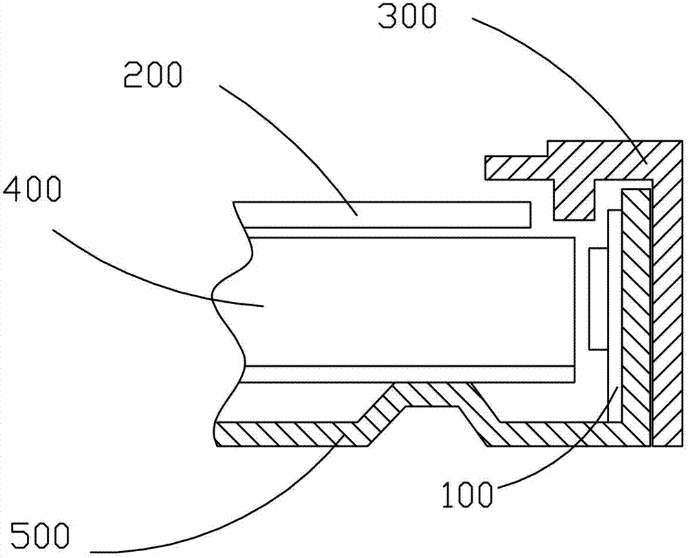
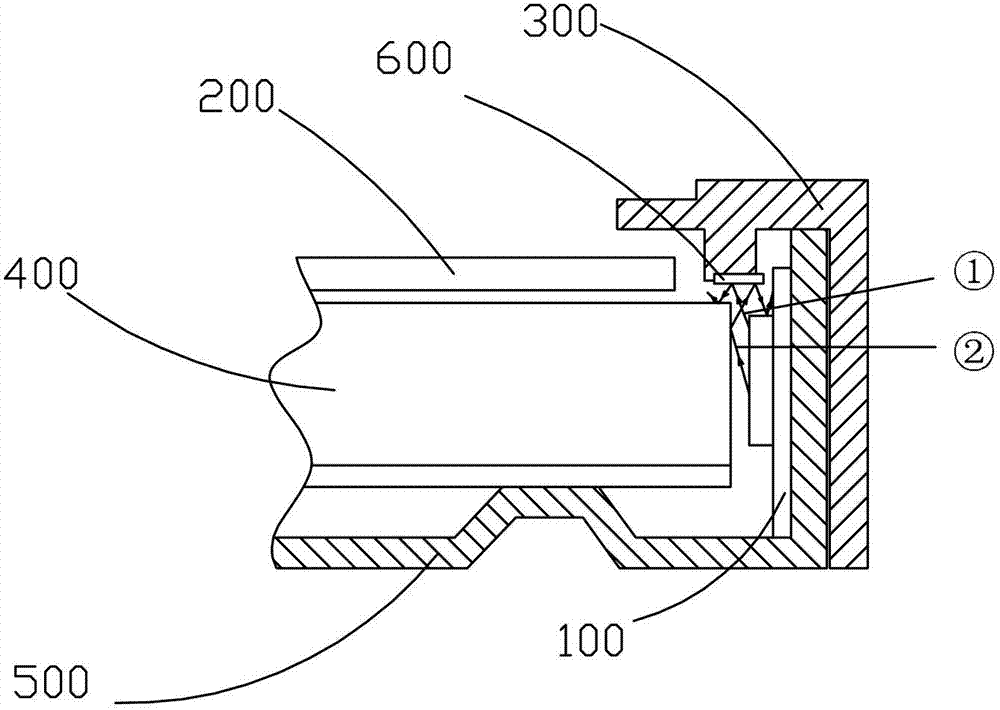
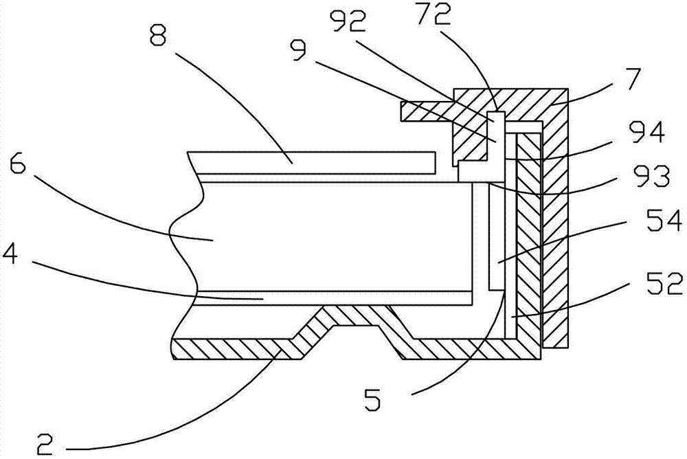
[0032] see image 3 , the present invention provides a backlight module, which includes: a backplane 2, a reflective sheet 4 arranged in the backplane 2, a light guide plate 6 arranged on the reflective sheet 4, an optical film group arranged on the light guide plate 6 8. The backlight 5 arranged in the backplane 2 and opposite to the light guide plate 6, the plastic frame 7 arranged on the backplane 2, and the backlight 5 and the light-incoming end of the light guide plate 6 are arranged above the light-incoming end and are tightly plugged and pasted. The elastic retaining wall 9 is attached or fixed on the plastic frame 7. The elastic retaining wall 9 includes a bottom surface 93 and a side surface 94 perpendicular to the bottom surface 93. ...


PUM


Abstract

The invention provides a backlight module. The backlight module comprises a back plate, a reflecting sheet arranged in the back plate, a light guide plate arranged on the reflecting sheet, an optical membrane assembly arranged on the light guide plate, a backlight source arranged in the back plate and facing the light guide plate, a frame arranged on the back plate, and an elastic retaining wall arranged above the light incident end of the backlight source and the light guide plate and fixed on the frame in a plugging, attaching or clamping manner, wherein the elastic retaining wall includes a bottom surface and a side surface vertical to the bottom surface; and the bottom surface and the side surface keep close contact with the upper surface of the light guide plate and the backlight source. The elastic retaining wall made of white rubber and having elasticity is fixed on the frame in the plugging, attaching or clamping manner and keeps close contact with the light guide plate and the upper surface of an LED (light emitting diode) lamp, so that the elastic retaining wall can reflect light back to the light guide plate to well prevent the light from being emitted from a gap on the light incident side, thereby solving the problem of incident-side light leakage of the backlight module and improving the light efficiency of the backlight module.

Description

technical field [0001] The invention relates to the field of liquid crystal displays, in particular to a backlight module for preventing light leakage. Background technique [0002] A liquid crystal display (LCD, Liquid Crystal Display) has many advantages such as a thin body, power saving, and no radiation, and has been widely used. Most of the liquid crystal display devices currently on the market are backlight liquid crystal display devices, which include a liquid crystal panel and a backlight module. The working principle of the liquid crystal panel is to place liquid crystal molecules between two parallel glass substrates. There are many vertical and horizontal small wires between the two glass substrates. The direction of the liquid crystal molecules is controlled by electrifying or not, and the light of the backlight module is refracted. Come out to generate the picture. Since the liquid crystal panel itself does not emit light, the light source provided by the back...

Claims


Application Information

Patent Timeline
Patent Type & Authority Applications(China)
IPC IPC(8): F21S8/00F21V17/16G02F1/13357F21Y101/02
CPCG02B6/0088G02B6/0093G02F1/1336G02F1/133615G02F1/133317
Inventor 萧宇均张庞岭巫越李全
Owner TCL CHINA STAR OPTOELECTRONICS TECH CO LTD
Why Eureka
Try Eureka