Boundary identification method for mowing robot

A lawn mowing robot and boundary recognition technology, applied in the field of robotics, to achieve the effect of ensuring the working range and simple method

Inactive Publication Date: 2013-01-23
SHANGHAI THERMO ECOTECH
View PDF0 Cites 27 Cited by
  • Summary
  • Abstract
  • Description
  • Claims
  • Application Information

AI Technical Summary

Problems solved by technology

[0007] The purpose of the present invention is to propose a boundary recognition method for a mowing robot to solve the problem that the mowing robot is reliably limited to mowing in a specified area

Method used


Image

  • Boundary identification method for mowing robot
  • Boundary identification method for mowing robot
  • Boundary identification method for mowing robot

Examples


Embodiment Construction

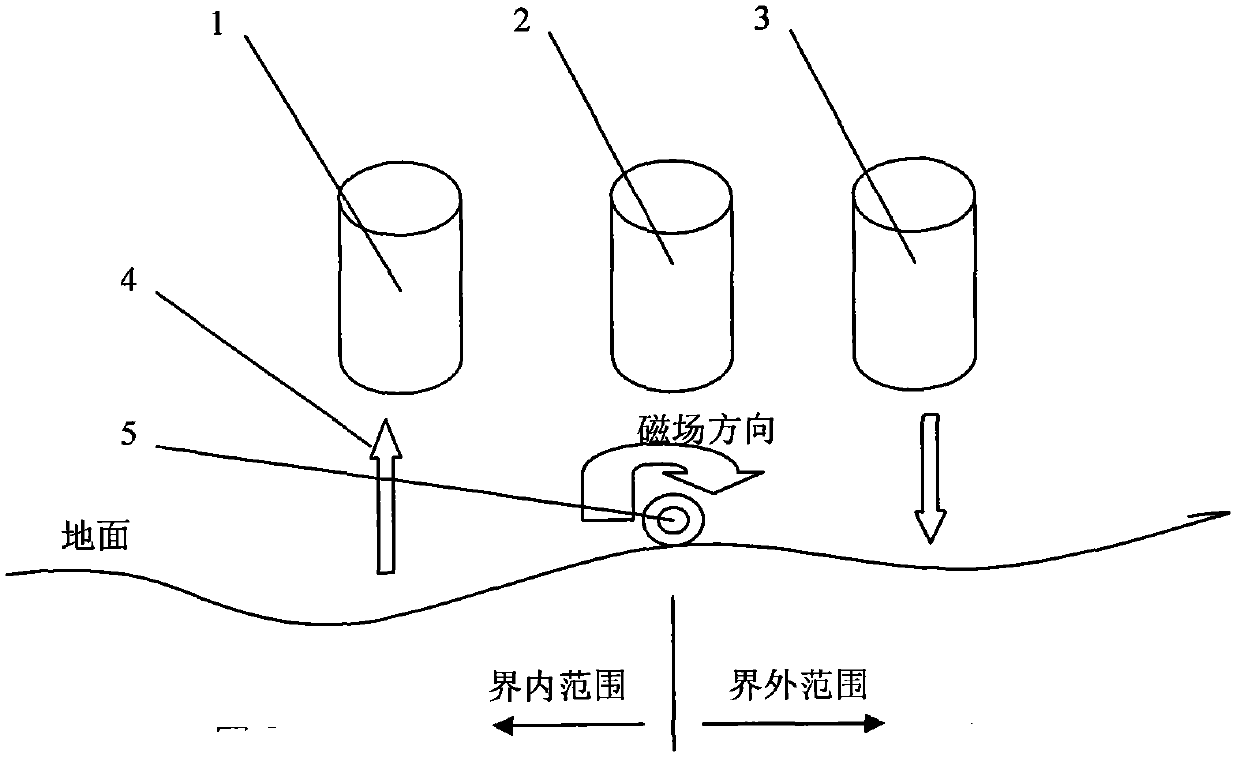
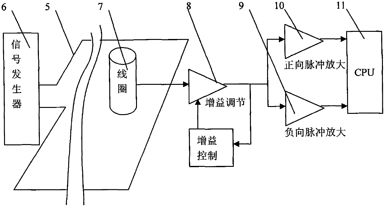
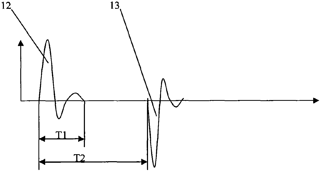
[0019] The following is attached figure 1 , 2 , 3, 4 and 5 give the example that the structure of the present invention is described in further detail.

[0020] The boundary signal generator (6) of the lawn mowing robot generates asymmetric electromagnetic pulses in a single direction, causing electromagnetic signal characteristics in opposite directions in areas inside or outside the boundary line. In the area enclosed by the boundary cable (5), a positive pulse (12) is generated, and outside the area enclosed by the boundary cable (5), a negative pulse (13) is generated.

[0021] When the mowing robot moves to these areas, the signal detected by the magnetic induction coil (7) carried by it is amplified by a variable gain amplifier circuit (8) and then output. The output signal end of the amplifying circuit (8) is connected to the input end of the gain control device, and the magnitude of the input signal generates feedback signals of different sizes at the output end to c...


PUM


Abstract

The invention provides a boundary identification method for a mowing robot. A signal generator of the mowing robot generates asymmetrically-unidirectional electromagnetic pulses which causes electromagnetic signal characteristics in opposite directions in a region in the range of a boundary line and a region out of the boundary line; a signal detection circuit is used for identifying characteristics of forward-direction magnetic induction signals and negative-direction magnetic induction signals, respectively; and the mowing robot is determined in the region in the range of the boundary line or the region out of the boundary line or right above the boundary line according to the characteristics. With the adoption of a variable gain amplification circuit, the magnetic induction signals are weak, amplifier gains are amplified, and outputs are increased, or the magnetic induction signals are strong, the amplifier gains are reduced, and the outputs are reduced, and therefore, the characteristics of the magnetic induction signals can be identified reliably in plane regions which are large enough, and the mowing robot can be determined in the region in the range of the boundary line or the region out of the boundary line.

Description

technical field [0001] The invention relates to a method for identifying the boundary of a mowing robot and belongs to the technical field of robots. Background technique [0002] The lawn mowing robot controls the working range of the lawn mowing robot by detecting or calculating boundary information through various sensors, and mows the grass in a specified area. [0003] Existing lawn mowing robots use magnetic induction sensors to detect the existence and disappearance of boundary lines, and calculate boundary information. The algorithm is complex and error-prone, causing the lawn mowing robot to rush out of the boundary and cannot return to the specified area, lacking effective boundary recognition method. [0004] In the existing mowing robot, the boundary signal is composed of symmetrical positive and negative electromagnetic pulses, and the signal recognition system cannot identify whether the magnetic induction sensor is in the circle surrounded by the boundary lin...

Claims


Application Information

Patent Timeline
Patent Type & Authority Applications(China)
IPC IPC(8): G01B7/28
Inventor 袁帆王福全
Owner SHANGHAI THERMO ECOTECH
Why Eureka
Try Eureka