Device and method for converting thermal energy

A heat energy and heat energy conversion technology, used in refrigeration and liquefaction, lighting and heating equipment, independent rotary compressors, etc., can solve the problem that the equipment cannot be the minimum length, and achieve the effect of high stability, space saving and size reduction

Active Publication Date: 2013-01-23
风和日暖科技有限责任公司
View PDF6 Cites 5 Cited by
  • Summary
  • Abstract
  • Description
  • Claims
  • Application Information

AI Technical Summary

Problems solved by technology

This has the disadvantage that the device cannot go below a minimum le

Method used


Image

  • Device and method for converting thermal energy
  • Device and method for converting thermal energy
  • Device and method for converting thermal energy

Examples


Embodiment Construction

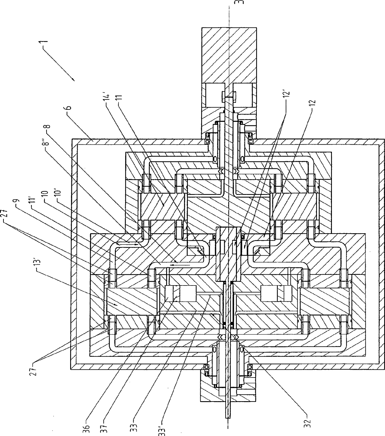
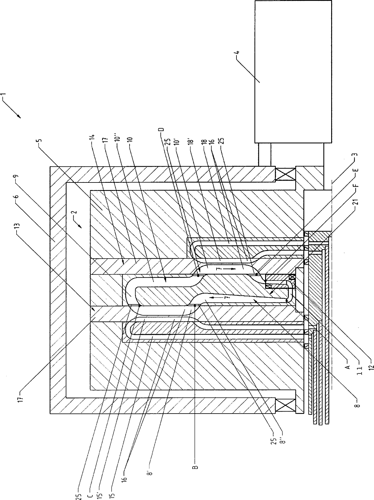
[0057] FIG. 1 shows a device 1 according to the invention for converting mechanical energy into thermal energy and vice versa, which is operated as a heat pump in the illustrated exemplary embodiment. The device 1 comprises a rotor 2 driven by a rotating shaft 3 of a motor 4 . The rotor 2 has a block-shaped rim 5 which is accommodated in an outer, stationary housing 6 . Closed flow channels for the working medium carrying out the circulating process, which is present in a gaseous state during the entire cycle, are formed in the rotor 2 . The working medium, eg argon, is guided clockwise or in the direction of the arrow 7 from the compression channel 8 via the first connecting channel 9 into the pressure-relief channel 10 , which is connected to the compression channel 8 via the second connecting section 11 middle. The compression channel 8 and the pressure relief channel 10 are respectively arranged approximately perpendicular to the axis of rotation 3 , while the connecting...


PUM


Abstract

The invention relates to a device (1) and a method for converting thermal energy of low temperature to thermal energy of high temperature by means of mechanical energy and vice versa, said device comprising a rotor (2) that is rotatably supported about a rotational axis (3), a flow channel for a working medium that runs through a closed cycle being provided in the rotor, wherein the flow channel has a compression channel (8), a relaxation channel (10), and two connection channels (9, 11) extending substantially parallel to the rotational axis (3), and furthermore heat exchangers (13, 14) for exchanging heat between the working medium and a heat-exchange medium are provided, wherein the compression channel (8) and the relaxation channel (10) each have a heat-exchange segment (8', 10'), each of which has a heat exchanger (13, 14) that rotates together with the compression channel (8); or the relaxation channel (10) associated therewith, said heat exchanger being formed by at least one heat-exchange channel (15, 18) that conducts the heat-exchange medium.

Description

technical field [0001] The invention relates to a device for converting lower-temperature thermal energy into higher-temperature thermal energy by means of mechanical energy and vice versa, with a rotor rotatably supported about an axis of rotation, in which a device for experiencing The flow channel of the working medium of the closed circuit process, wherein the flow channel has: a compression channel, in which the working medium can be guided approximately radially outwards with respect to the axis of rotation for a pressure increase; a pressure-relief channel, in which the working medium for The pressure reduction can be directed approximately radially inwards with respect to the axis of rotation; and two connecting channels extending approximately parallel to the axis of rotation and additionally provided with a heat exchanger for heat exchange between the working medium and the heat exchange medium, wherein the compression The channel and the decompression channel each h...

Claims


Application Information

Patent Timeline
IPC IPC(8): F25B3/00F25B9/00
CPCF25B3/00F25B9/00
Inventor B.艾德勒S.里普尔
Owner 风和日暖科技有限责任公司
Why Eureka
Try Eureka