Mechanical automatic feeding and discharging device

An automatic loading and unloading, mechanical technology, applied in metal processing and other directions, can solve the problems of wasting manpower, the safety of staff cannot be effectively guaranteed, and the work efficiency is low.

Inactive Publication Date: 2013-01-30
CHANGZHOU LIWEI KNIFE
View PDF5 Cites 2 Cited by
  • Summary
  • Abstract
  • Description
  • Claims
  • Application Information

AI Technical Summary

Problems solved by technology

[0002] In the existing workshop, the upper and lower parts of the workpiece are manually realized. This method is subject to a greater degree of subjective influence, and it is not easy to accurately grasp the feeding time. Moreover, the safety o

Method used


Image

  • Mechanical automatic feeding and discharging device

Examples


Embodiment Construction

[0013] The present invention will be further described below in conjunction with the accompanying drawings and specific embodiments.

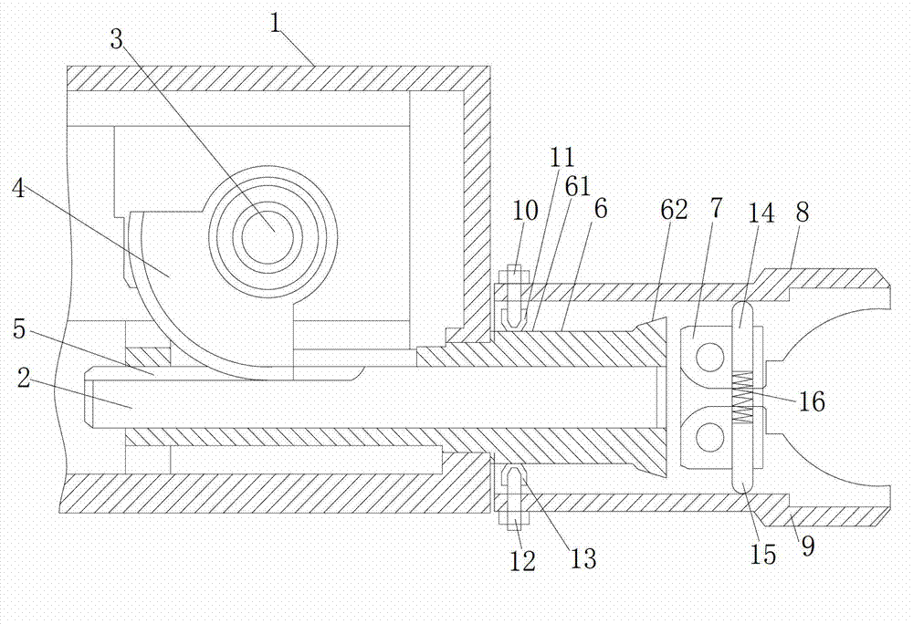
[0014] see figure 1 , a mechanical automatic loading and unloading device, the device includes a base 1, a transmission shaft 2, one end of the transmission shaft 2 extends into the base, the other end extends outside the base, and the transmission shaft is set on the base to drive the shaft back and forth A driving mechanism for movement, the driving mechanism includes a driving shaft 3 arranged on the base 1, a driving gear 4 fixedly arranged at one end of the driving shaft 3, and a tooth groove 5 matched with the driving gear 4 is arranged on the transmission shaft 2;

[0015] A guide sleeve 6 for guiding the transmission shaft 2 is fixedly arranged on the base 1. The outer diameter of one end 61 of the guide sleeve 6 is smaller than the outer diameter of the other end 62. The end of the transmission shaft 2 exposed from the base passes thro...


PUM


Abstract

The invention relates to a mechanical automatic feeding and discharging device which comprises a base, a transmission shaft and a driving mechanism, wherein one end of the transmission shaft stretches into the base; the other end of the transmission shaft stretches to the outside of the base; the driving mechanism is used for driving the transmission shaft to move; a guide sleeve for guiding the transmission shaft is arranged on the base; the outer diameter of the guide sleeve is less than the outer diameter of the other end of the guide sleeve; one end of the transmission shaft which is exposed outside the base penetrates through the guide sleeve; a finger fixing sleeve is arranged at the end part of the transmission shaft which stretches outside the guide sleeve; an upper finger is movably connected with the upper part of the finger fixing sleeve; a lower finger is connected with the lower part of the finger fixing sleeve; the left ends of the upper finger and the lower finger extend to the guide sleeve; an expanding device is arranged at the left ends of the upper finger and the lower finger; and a recovery device is arranged on the finger fixing sleeve and is used for recovering the upper finger and the lower finger. With the adoption of the device, a workpiece can be clamped and released automatically, the feeding and discharging time can be mastered accurately, the sufficient utilization rate and the working efficiency of equipment are improved, and meanwhile a great deal of labor is not wasted.

Description

technical field [0001] The invention relates to the technical field of machining equipment, in particular to a mechanical automatic loading and unloading device used in machining. Background technique [0002] In the existing workshop, the upper and lower parts of the workpiece are manually realized. This method is subject to a greater degree of subjective influence, and it is not easy to accurately grasp the feeding time. Moreover, the safety of the staff cannot be effectively guaranteed during the manual loading and unloading process. , it often occurs that the staff is injured by the machine, the work efficiency of manual loading and unloading is low, and a lot of manpower is wasted. Contents of the invention [0003] In view of the above technical problems, the present invention provides a mechanical automatic loading and unloading device, which can automatically load and unload workpieces, accurately grasp the loading and unloading time, improve the full utilization r...

Claims


Application Information

Patent Timeline
IPC IPC(8): B23Q7/04
Inventor 周建国夏利荣
Owner CHANGZHOU LIWEI KNIFE
Why Eureka
Try Eureka