Keyboard key full-pattern injection mold structure and system thereof

An injection mold and injection system technology, applied in the field of injection mold structure and its system, can solve the problems of occupying inventory space, increasing labor costs, reducing production efficiency, etc., and achieving the effect of reducing weight, reducing subsequent processes, and improving production efficiency

Inactive Publication Date: 2013-01-30
SHENZHEN RAPOO TECH
View PDF5 Cites 2 Cited by
  • Summary
  • Abstract
  • Description
  • Claims
  • Application Information

AI Technical Summary

Problems solved by technology

The keycap molds in the industry usually use one set of molds for each type of keycap. The number of molds is large, the production efficiency is low, and the labor cost is increased and the injection molding machine is occupied.
From the perspective of assembly, the current keycap assembly traditionally relies on manual assembly, and the more advanced technology only relies on the vibration plate to assemble the keycaps, and the function keys still need manual assembly.
And this assembly method needs to prepare and transport materials to the assembly workshop, which takes up inventory space and reduces production efficiency

Method used


Image

  • Keyboard key full-pattern injection mold structure and system thereof
  • Keyboard key full-pattern injection mold structure and system thereof
  • Keyboard key full-pattern injection mold structure and system thereof

Examples


Embodiment Construction

[0076] In order to fully understand the technical content of the present invention, the technical solutions of the present invention will be further introduced and illustrated below in conjunction with specific examples, but not limited thereto.

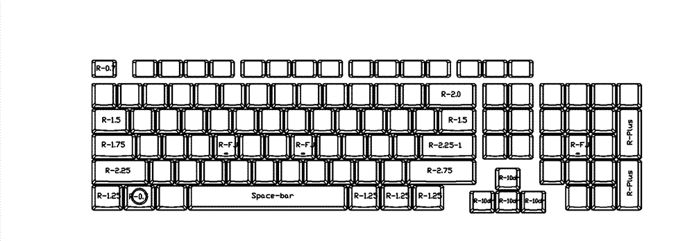
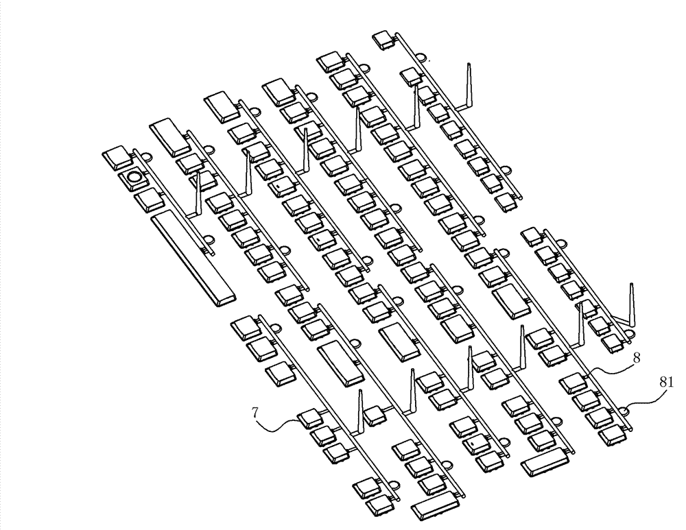
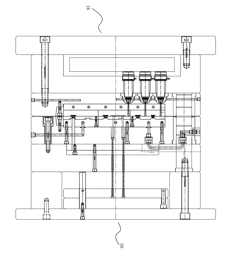
[0077] Such as Figure 3 to Figure 12 As shown, the whole-page injection mold structure of the keyboard button of the present invention includes a front mold base 91 and a rear mold base 92. Including the rear mold base 921 and the rear mold core 922 fixed on the rear mold base 921, between the front mold core 912 and the rear mold core 922 are provided with several molding cavities for forming the keys of the entire keyboard, and are connected to several The hot runner of the molding cavity, the hot runner communicates with the hot nozzle 913 located at the front mold base 911, the molding cavity is divided into several rows, and the row spacing between each row of molding cavities is greater than the row spacing of the keys on the ...


PUM


Abstract

The present invention discloses a keyboard key full-pattern injection mold structure and a system thereof. The keyboard key full-pattern injection mold structure comprises a front mold frame and a rear mold frame, wherein the front mold frame comprises a front mold holder and a front mold core fixed on the front mold holder, and the rear mold frame comprises a rear mold holder and a rear mold core fixed on the rear mold holder. A plurality of molding mold cavities for forming keys of the whole keyboard and a plurality of hot runners communicated between the plurality of the molding mold cavities are arranged between the front mold core and the rear mold core, wherein the hot runners and a hot sprue arranged on the front mold holder are communicated, the molding mold cavities are divided into a plurality of rows, the row distance of the molding mold cavity is greater than the row distance of the keys on the keyboard, and the interval of the molding mold cavity is further greater than the interval of the keys on the keyboard. According to the present invention, the key production of the whole keyboard can be solved by only requiring a set of the mold, and fully automated direct assembly of the followed segments is completely considered, such that all the key caps can be assembled without manual assembly so as to improve production efficiency; and transference stock of the keys is canceled, wherein the key caps are required to be subjected to warehousing after injection molding, and then are assembled by receiving the material through the assembly workshop.

Description

technical field [0001] The present invention relates to an injection mold structure and its system, more specifically to an injection mold structure and its system for injection molding the full-page keys on a keyboard. Background technique [0002] At present, in the field of keyboard production technology, most manufacturers generally use small molds to produce keyboard keys, and then use professional installation production lines to assemble different keys on a keyboard. Due to the large number of keys on the keyboard, such a production method will increase a lot of processes and need to consume a lot of manpower and material resources; thereby indirectly increasing the cost of the keyboard. The keycaps of a keyboard are generally assembled from at least 13 kinds of keycaps. The keycap molds in the industry usually use one set of molds for each type of keycap. The number of molds is large, the production efficiency is low, and the labor cost is increased and the injectio...

Claims


Application Information

Patent Timeline
IPC IPC(8): B29C45/32B29C45/27B29C45/03B29C45/40
Inventor 廖月华
Owner SHENZHEN RAPOO TECH
Why Eureka
Try Eureka