Vibration isolating unit for vehicle

A vibration isolation and vehicle technology, applied in non-rotational vibration suppression, mechanical equipment, machine/engine, etc., can solve problems such as increased fuel consumption

Inactive Publication Date: 2013-01-30
NISSAN MOTOR CO LTD
View PDF7 Cites 6 Cited by
  • Summary
  • Abstract
  • Description
  • Claims
  • Application Information

AI Technical Summary

Problems solved by technology

[0004] However, in the conventional vibration isolation device described above, since the driving power of the driver is supplied from the bat...

Method used


Image

  • Vibration isolating unit for vehicle
  • Vibration isolating unit for vehicle
  • Vibration isolating unit for vehicle

Examples


Embodiment Construction

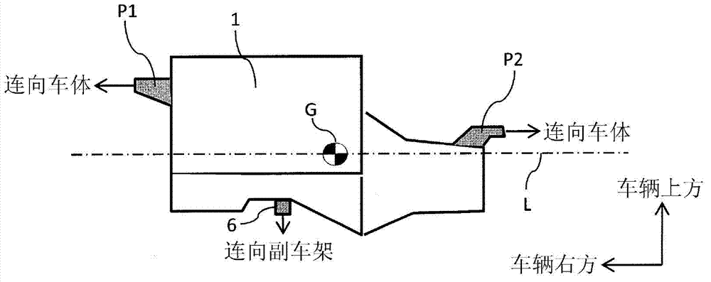
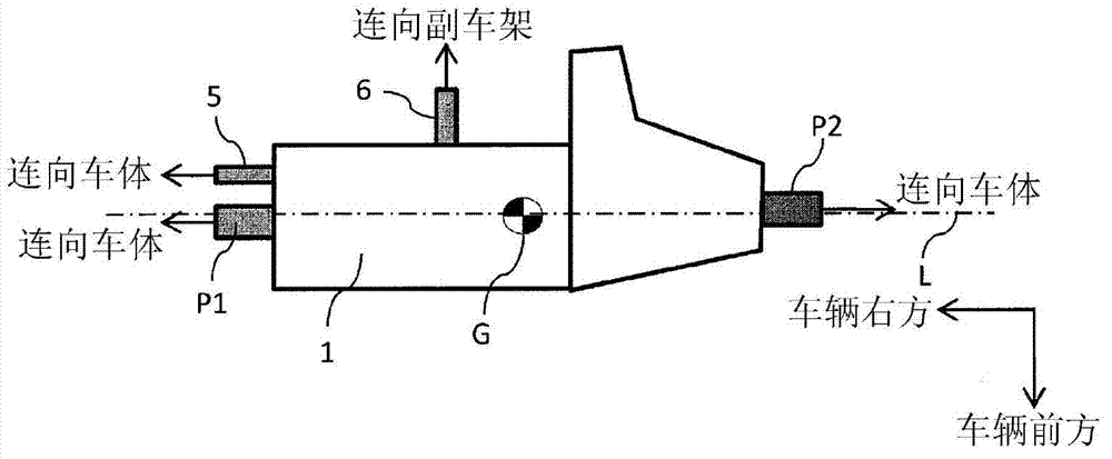
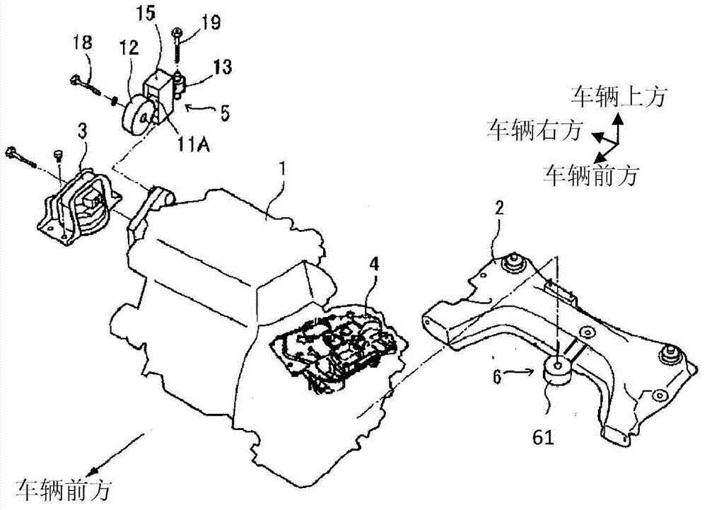
[0027] First, a so-called pendulum engine to which a vibration isolating device for a vehicle according to an embodiment of the present invention is applied will be described. Such as Figure 1A and Figure 1B As shown, the support structure of the engine 1 adopting a pendulum type is a so-called lateral direction that arranges the main axis of inertia L of the engine 1 parallel to the width direction of the vehicle (the direction perpendicular to the direction of travel, also referred to as the vehicle left-right direction). As far as the engine 1 is concerned, the two support points P1 and P2 supporting the engine 1 are at Figure 1B is located near the main axis of inertia L of the engine 1 in a plan view, and is on the opposite side of the axis across the center of gravity G. Figure 1A In the side view of , the two support points P1, P2 are located above the vehicle of the main axis of inertia L. In addition, the two supporting points P1 and P2 are as figure 2 It is sh...


PUM


Abstract

The invention provides a vibration isolating unit for vehicles. Driving power of an actuator can be reduced by the device. The vibration isolating unit for vehicles comprise a rod (11) with one end (12) thereof fixed on an engine (1) and the other end (13) fixed on the vehicle body; an inertia block (15) supported on the rod (11); an actuator (17) for driving the inertia block to move backward and forward in an axis direction of the rod; an electric control component (26) for driving the actuator; and an electric power storage component (26) for supplying electric power to the electric control component; wherein the actuator does not drive, the electric control component converts vibration of the inertia block into electric power and charge the electric power into the electric power storage component.

Description

technical field [0001] The present invention relates to a vibration isolating device for a vehicle for suppressing vibration transmitted from an engine as a vibration source to a vehicle body side. Background technique [0002] As a vibration isolating device that suppresses the vibration transmitted from the engine to the vehicle body side, a vibration isolating device is proposed in which the rigid body resonance frequency of the torsion bar is set lower than the resonance frequency of the engine, and a torsion force is generated in the driver. The speed of axial displacement of the rod is proportional to the force (Patent Document 1). [0003] Patent Document 1: Japanese Unexamined Patent Publication No. 2011-12757 [0004] However, in the conventional vibration isolation device described above, since the driving power of the driver is supplied from the battery mounted on the vehicle, there is a problem that the fuel consumption of the vehicle increases by the amount cor...

Claims


Application Information

Patent Timeline
IPC IPC(8): F16F15/02F03G7/08
CPCF03G7/08
Inventor 佐藤裕介金堂雅彦
Owner NISSAN MOTOR CO LTD
Why Eureka
Try Eureka