
All-angle and distance-adjustable non-contact excitation experiment platform

An experimental platform and adjustable technology, which is applied in the field of non-contact excitation experimental platform with adjustable full angle and distance, can solve the problem that affects the authenticity and accuracy of experimental data, cannot meet the needs of scientific research, and the distance between the exciter and the excited parts Problems such as inability to make precise adjustments

Active Publication Date: 2013-01-30
ZHEJIANG UNIV
View PDF8 Cites 9 Cited by
  • Summary
  • Abstract
  • Description
  • Claims
  • Application Information

AI Technical Summary

Problems solved by technology

At present, in the existing non-contact vibration test platform for vibration experiments on moving parts, there are mainly the following problems: the non-contact vibration exciter is fixedly installed, and its installation position cannot be flexibly changed according to the position of the moving parts, which leads to The distance between the exciter and the excited part cannot be adjusted precisely
When the distance between the exciter and the excited part is too close, it is easy to cause the vibrator to be directly adsorbed on the excited part, causing the excitation experiment to be interrupted. When the distance between the vibrator and the excited part is too far, the excited The excitation signal received by the component is poor, and the excitation effect is not obvious
The above two situations will affect the authenticity and accuracy of the experimental data, so that the experimenters cannot obtain correct experimental results based on the experimental data
The fixed installation form of the non-contact vibrator can only perform one-way excitation experiments on the excited parts, and cannot conduct full-angle excitation experiments. The obtained experimental data is single, which cannot meet the needs of scientific research

Method used


Image

  • All-angle and distance-adjustable non-contact excitation experiment platform
  • All-angle and distance-adjustable non-contact excitation experiment platform
  • All-angle and distance-adjustable non-contact excitation experiment platform

Examples


Embodiment Construction

[0021] The present invention will be described in further detail below in conjunction with the accompanying drawings and specific embodiments.

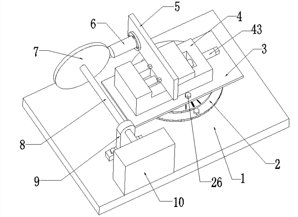
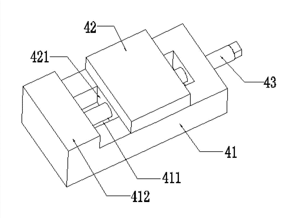
[0022] As shown in the figure, the full angle and distance adjustable non-contact vibration excitation experiment platform includes a base 1, an angle adjustment device 2, a connecting plate 3, a displacement adjustment device 4, a positioning plate 5 and a non-contact vibration exciter 6.

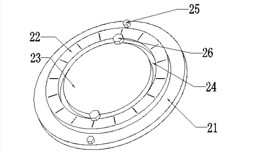
[0023] The angle adjustment device 2 includes a turntable seat 21, a dial 22, a clamping disc 23, a fixing bolt 25 and a clamping bolt 26, the turntable seat 21 is fixed on the base by the fixing bolt 25, and the dial 22 is fixedly mounted on the turntable seat 21. The clamping disc 23 is also fixedly arranged on the turntable base 21 . The dial 22 is annular, and its inner diameter is larger than that of the clamping disc. The gap between the dial 22 and the clamping disc 23 forms a circular track 24 . The connecting plate 3 is movably installed...


PUM


Abstract

The invention provides an all-angle and distance-adjustable non-contact excitation experiment platform, which comprises a base, an angle adjusting device, a connecting plate, a displacement adjusting device, a locating plate and a non-contact exciter. The connecting plate is movably mounted on the angle adjusting device; the displacement adjusting device is mounted on the connecting plate; and the non-contact exciter is mounted on the displacement adjusting device by the locating plate. According to the invention, the distance and the angle of the non-contact exciter are adjusted; according to the position of an excited part, the direction of the non-contact exciter is first adjusted and then the distance between the non-contact exciter and the excited part is adjusted, so that an optimal experiment effect is achieved, the authenticity and accuracy of experiment data are enhanced and scientific research and experimental requirements are satisfied.

Description

technical field [0001] The invention relates to an experimental device, in particular to a non-contact vibration excitation experimental platform with adjustable full angle and distance. Background technique [0002] The mechanical system vibration experiment platform is used to simulate the environment in which mechanical parts are in the actual working process. It is used in many scientific experiment fields, including vibration resistance test, reliability experiment, vibration simulation analysis and fatigue experiment of various mechanical equipment. , material characteristic test, fault diagnosis and life prediction, etc. Most of the vibrating tables currently available on the market and existing in various scientific research institutions are contact vibration tables. The vibration excitation equipment of this type of experimental platform usually needs to use the transmission rod to contact the excited part to transmit the excitation signal. Therefore, this type of v...

Claims


Application Information

Patent Timeline
Patent Type & Authority Applications(China)
IPC IPC(8): G01M7/06
Inventor 杨世锡何俊甘春标黄其祥熊炘
Owner ZHEJIANG UNIV
Learn More