
Integrated high-power signal source

A signal source, high-power technology, applied in transmission monitoring, comprehensive factory control, electrical components, etc., can solve the problems of ALC loop design circuit complexity, high cost, power device final stage power tube damage, etc.

Active Publication Date: 2022-05-31
10TH RES INST OF CETC
View PDF6 Cites 1 Cited by
  • Summary
  • Abstract
  • Description
  • Claims
  • Application Information

AI Technical Summary

Problems solved by technology

Therefore, there is a fluctuating process before the steady state. During this process, the gain of the power amplification link changes greatly. Because the voltage-controlled attenuator cannot withstand excessive input power, it may affect the power device, especially the final power. tube damage
At present, the ALC loop control circuit mainly includes a variable gain device, a power amplifier, a detection circuit, a reference preset circuit, a power amplifier detection voltage processing circuit, and a filter circuit. The above circuits form a negative feedback loop, so the ALC loop The design circuit is complex and the cost is high
And after the ALC loop works, the power amplifier works in a linear state, that is, the maximum power of the power amplifier needs to be greater than the output power after the ALC works, usually >0.5dB, because there is no integrated high-power signal source for this frequency band on the market. , it is urgent to develop an integrated high-power signal source, which is used for the power resistance assessment test of products and components

Method used


Image

  • Integrated high-power signal source
  • Integrated high-power signal source
  • Integrated high-power signal source

Examples


Embodiment Construction

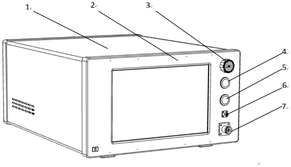
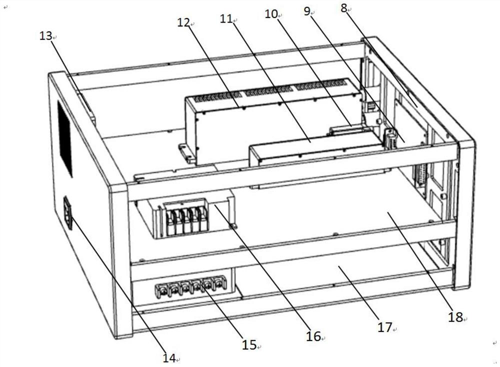
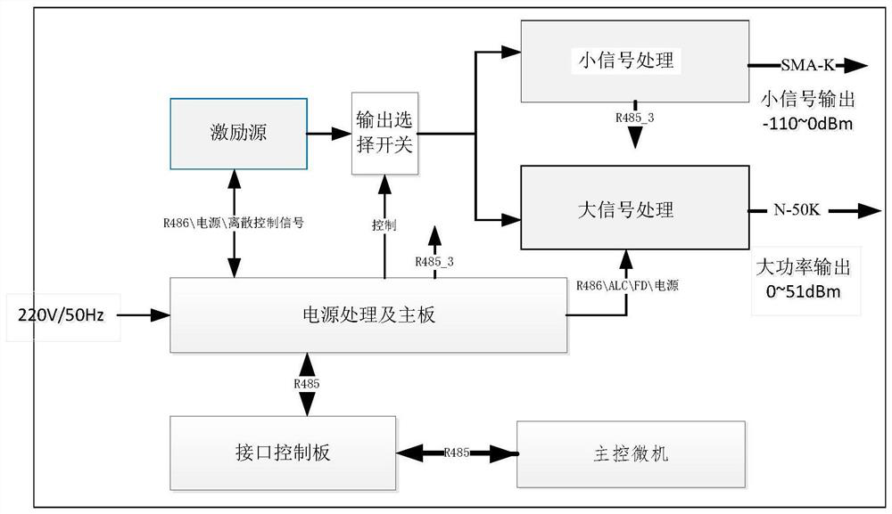
[0019] see Figure 1 to Figure 3 . In the preferred embodiment described below, an integrated high-power signal source instrument device includes: a power knob button 3 arranged on the front panel 2 of the chassis 1, a signal selection button 4, a transceiver button 5, a small signal output The interface SAM 6, the N-type large signal output interface 7, and the signal source power interface 14 on the side panel are fixed on the inner side wall of the chassis 1, and are arranged on the chassis mounting fixture 18, the 5V power module 16 and the 28V power supply below it Module 15, connected to the main control microcomputer 8 of the interface control module 9, connected in parallel with the power supply processing and the main board 17 and the excitation source module 11 and the output selection switch on the main board, connected to the small signal processing module 10 of the output selection switch and the large signal processing module 10 The module 12 is characterized in...


PUM


Abstract

According to the integrated high-power signal source disclosed by the invention, two kinds of signal amplitude signals of 110 to 0dBm and 0 to 51dBm and the frequency of 30 to 512MHz can be output. According to the technical scheme, an excitation source module and a large signal processing module are electrically connected with a power supply processing and mainboard, and a master control microcomputer is connected with an interface control module, the excitation source module, the large signal processing module and a 5V power supply module through a serial port bus. The interface control module processes a command issued by the main control microcomputer and then issues the command to the power supply processing and mainboard through a bus; the excitation source module, the small signal processing module and the large signal processing module realize control of signal source signal frequency, large / small signal mode and power gear; the excitation source module, the small signal processing module and the large signal processing module return data, an output control result of a signal source is reported to the main control microcomputer through the interface control module, and output of large-power signals is achieved through a signal selection key and a transceiving key on a panel.

Description

technical field [0001] The invention belongs to the field of radio product debugging instruments and equipment, and relates to an integrated high-power signal instrument and equipment that provides a frequency of 30-512 MHz and an output signal of -110-0dBm and 0-51dBm. In particular, it involves the power resistance assessment test of RF components such as filters, RF switches and limiters in the UV frequency band, the whole machine and sub-system; at the same time, it can be used as an integrated high-power signal source instrument and equipment used as a small-signal excitation source. Background technique [0002] UV-band high-power RF components such as high-power RF distribution units, electronic switches, and co-located filter components are widely used in aviation and aerospace communication equipment. Such RF components often require high-reliability performance requirements such as "large input power, low loss, long life, safety and reliability". Based on this hig...

Claims


Application Information

Patent Timeline
IPC IPC(8): H04B17/00H04Q1/02H04Q1/20
CPCH04B17/0085H04Q1/028H04Q1/03H04Q1/035H04Q1/135H04Q1/20Y02P90/02
Inventor 谭晓明杨青山肖华周阳明徐豪高敏
Owner 10TH RES INST OF CETC
Learn More