Supercharge Your Innovation With Domain-Expert AI Agents!

Touch detection component, touch control device and portable electronic equipment

A touch detection and component technology, applied in electrical digital data processing, instruments, calculations, etc., can solve problems such as small capacitance change, offset in coordinate calculation, and insufficient linearity, and achieves improved linearity and linearity. , the effect of improving the measurement accuracy

Inactive Publication Date: 2013-01-30
BYD SEMICON CO LTD
View PDF4 Cites 1 Cited by
  • Summary
  • Abstract
  • Description
  • Claims
  • Application Information

AI Technical Summary

Problems solved by technology

Although the self-capacitive touch detection component has a simple structure, it is not optimized for the capacitive sensing of the screen, and the capacitance change is small, resulting in insufficient signal-to-noise ratio
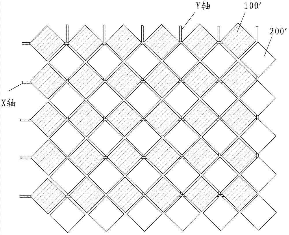
In addition, since the sensing unit is a triangle, the area does not increase linearly when the finger moves laterally, so the linearity is poor, which leads to the offset of the coordinate calculation, and the linearity is not good enough
[0006] In addition, the capacitance change output by the traditional capacitance sensing unit is very small, reaching the femtofarad level, and the existence of stray capacitance in the cable puts forward higher requirements for the measurement circuit
Moreover, stray capacitance will change with many factors such as temperature, location, internal and external electric field distribution, etc., which will interfere or even submerge the measured capacitance signal

Method used


Image

  • Touch detection component, touch control device and portable electronic equipment
  • Touch detection component, touch control device and portable electronic equipment
  • Touch detection component, touch control device and portable electronic equipment

Examples


Embodiment 1

[0083] In this embodiment, the plurality of hollowed out parts 24 are divided into a first group 24a and a second group 24b arranged linearly along the extending direction, and the hollowed out parts 24a in the first group and the hollowed out parts 24b in the second group are in the extending direction Alternately arranged and partially overlapped in the direction perpendicular to the extending direction, in other words, each of the hollowed out parts 24a in the first group is arranged between two adjacent hollowed out parts 24b in the second group, and the hollowed out parts 24a in the first group The hollow part 24a extends from the upper edge of the sensing body 20 toward the lower edge of the sensing body 20 in the width direction of the sensing body 20, and the hollow part 24a in the first group is spaced apart from the lower edge of the sensing body 20, and in the second group The hollow part 24b of the induction body 20 extends from the lower edge of the induction body ...

Embodiment 2

[0094] In this embodiment, the sensing body 20 has a first end and a second end, the first electrode 21 is connected to the first end of the sensing body 20, the second electrode 22 is connected to the second end of the sensing body 20, and the current path part 25 Extending in a curvilinear manner between the first and second ends so that the length L of the current path portion 25 is greater than the length of the induction body 20 in the extending direction of the current path portion 25 .

[0095] Wherein, the current path portion 25 extends between the first end and the second end and has a cross-sectional area on a plane perpendicular to its extending direction smaller than the cross-sectional area of ​​the induction body 20 on the plane, in other words, the current path portion 25 is vertically vertical. The width h in the direction is smaller than the width of the sensing body 20 . For example, when the sensing body 20 is rectangular, its length direction is the direct...

Embodiment 3

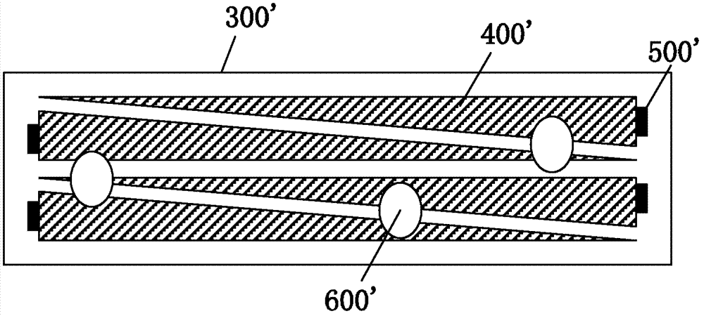
[0104] In this embodiment, there are two current path portions 25, one of which is adjacent to one side of the induction body 20 extending along the extension direction, and the other current path portion 25 is adjacent to one side of the induction body 20 extending along the extension direction. Another side. As a result, the total length of the current path portion 25 , that is, the length of the current flow path increases and the width decreases. For example, when the sensing body 20 is a rectangle, such as Figure 15-17 As shown, one of the current path portions 25 is adjacent to the upper side of the sensing body 20 and extends along the left-right direction, while the other current path portion 25 is adjacent to the lower side of the sensing body 20 and extends along the left-right direction.

[0105] Optionally, a plurality of hollowed out parts 24 are arranged linearly along the extending direction, and each hollowed out part 24 is substantially X-shaped, such as F...


PUM


Abstract

The invention discloses a touch detection component comprising a substrate and a plurality of sensing units. The sensing units are arranged on the substrate without interaction. Each sensing unit comprises a sensing body, a first electrode and a second electrode, wherein the sensing body is provided with a first end and a second end, the first electrode is connected with the first end of the sensing body, the second electrode is connected with the second end of the sensing body, the sensing body is provided with a plurality of hollowed-out portions, the hollowed-out portions are arranged by a preset rule so as to limit a current path portion for increasing resistance between the first electrode and the second electrode on the sensing body, the current path portion extends between the first end and the second end of the sensing body in a curved way, and sectional area of the current path portion on a plane orthogonal with the extending direction is smaller than that of the sensing body on the plane. According to the touch detection component in the embodiment, resistance required by detection accuracy can be obtained, and sensing linearity is improved. The invention further discloses a touch control device and portable electronic equipment.

Description

technical field [0001] The invention relates to the technical field of electronic equipment design and manufacture, and in particular to a touch detection component, a touch control device with the touch detection component, and a portable electronic device. Background technique [0002] Currently, touch detection components (touch screens) are used in electronic devices such as mobile phones, PDAs (Personal Digital Assistants), GPS (Global Positioning System), PMPs (MP3, MP4, etc.), and even tablet computers. The touch screen has the advantages of simple, convenient and humanized touch operation, so the touch screen is expected to become the best interface for human-computer interaction and has been widely used in portable devices. [0003] Capacitive touch detection components are generally classified into two types: self-capacitive and mutual-capacitive. The existing single-layer self-capacitance touch screen has strip-shaped scan electrodes made of ITO (Indium Tin Oxide...

Claims


Application Information

Patent Timeline
Patent Type & Authority Applications(China)
IPC IPC(8): G06F3/044
CPCG06F3/041G06F3/045G06F3/044G06F3/0443G06F3/0448
Inventor 李振刚黄臣杨云
Owner BYD SEMICON CO LTD
Features
  • R&D
  • Intellectual Property
  • Life Sciences
  • Materials
  • Tech Scout
  • Unparalleled Data Quality
  • Higher Quality Content
  • 60% Fewer Hallucinations
Learn More