Four-channel KB microimaging system working under small-size backlight

A microscopic imaging, four-channel technology, used in γ-ray or X-ray microscopy, nuclear engineering, etc., can solve the problems of inability to meet the requirements of backlight X-ray flux, high X-ray intensity, and reduced backlight X-ray intensity. It can achieve the effect of great difficulty in installation and adjustment, reduce the difficulty of installation and adjustment, and improve the intensity of backlight X-rays

Active Publication Date: 2013-01-30
TONGJI UNIV
View PDF3 Cites 11 Cited by
  • Summary
  • Abstract
  • Description
  • Claims
  • Application Information

AI Technical Summary

Problems solved by technology

Foreign strong laser devices use multiple lasers to drive the backlight target to obtain the backlight X-ray size on the order of millimeters, but the existing strong laser devices in my country only have one laser as the driving source of the backlight X-ray, and the laser uses point focus The size of the backlight X-rays obtained in the array mode is only about 400 μm, but the X-ray intensity per unit area is relatively high; although the size of the backlight X-rays is increased to the order of millimeters in the array mode, the corresponding backlight X-ray intensity per unit area is significantly reduced. Therefore, it cannot meet the requirements of the time-resolved ICF physics experiment on the backlight X-ray flux

Method used


Image

  • Four-channel KB microimaging system working under small-size backlight
  • Four-channel KB microimaging system working under small-size backlight
  • Four-channel KB microimaging system working under small-size backlight

Examples


Embodiment 1

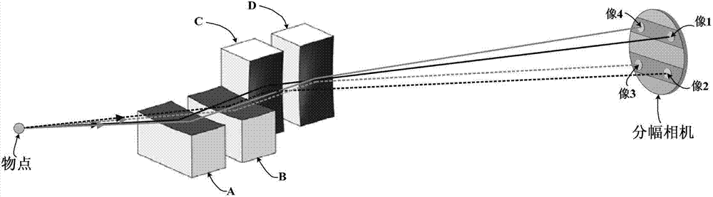
[0028] A four-channel KB microscopic imaging system operating under a small size backlight, such as image 3 As shown, it includes two KB objective lenses arranged in sequence in the meridional direction (namely objective lens A and objective lens B) and two KB objective lenses arranged in sequence in the sagittal direction (namely objective lens C and objective lens D). The X-rays emitted by the object point are respectively reflected by two KB objective lenses (namely objective lens A and objective lens B) in the meridional direction to form two-channel one-dimensional imaging, and then the two-channel one-dimensional imaging passes through the sagittal direction The two KB objective lenses (namely objective lens C and objective lens D) reflect and form four-channel two-dimensional imaging on the receiving surface of the framing camera. The specific imaging relationship is as follows: objective lens A and objective lens C participate in forming image 1; objective lens A and ...


PUM


Abstract

The invention relates to a four-channel KB microimaging system working under small-size backlight. The four-channel KB microimaging system comprises two KB objective lenses which are arranged in the meridian direction in sequence and two KB objective lenses which are arranged in the sagittal direction in sequence; and X ray emitted by an object point is respectively reflected by the two KB objective lenses in the meridian direction to form one-dimensional imaging of the two channels, and then the one-dimensional imaging of the two channels is respectively reflected by the two KB objective lenses in the sagittal direction to form two-dimensional imaging of the four channels. Compared with the prior art, the four-channel KB microimaging system has the advantages that the four KB objective lenses are arranged in sequence and are not interfered in space, so that the installation difficulty is also reduced, the requirement of the four-channel KB system on the size of the X ray of the backlight is obviously reduced, the intensity of the X ray of the backlight on the unit area is also correspondingly increased, the application range of the four-channel KB system in an ICF (Inertial Confined Fusion) physical experiment is expanded; and the four-channel KB microimaging system is suitable for being used on the current intense laser devices in China.

Description

technical field [0001] The invention relates to a four-channel X-ray microscopic imaging system for ICF plasma diagnosis, in particular to a four-channel KB microscopic imaging system working under a small size backlight. Background technique [0002] X-ray backlight imaging is an important diagnostic tool for high energy density physics (HEDP) and inertial confinement fusion (ICF) research. The four-channel KB microscopic imaging system is the key equipment for time-framing high-temperature and high-density plasma diagnosis in inertial confinement fusion (ICF) research, and has been widely used in OMEGA in the United States. The four-channel KB microscopic imaging system cooperates with the framing camera to achieve time resolution by sequentially responding to the four images at different times, showing the instantaneous state of the plasma in the two-dimensional space. The objective lens structure of the existing four-channel KB system is as follows: figure 1 As shown, ...

Claims


Application Information

Patent Timeline
Patent Type & Authority Applications(China)
IPC IPC(8): G21K7/00
Inventor 伊圣振穆宝忠王占山章逸舟王新
Owner TONGJI UNIV
Why Eureka
Try Eureka