Middle-arranged-type high-voltage switch cabinet
A high-voltage switchgear, center-mounted technology, applied to substation/switchgear board/panel/desk, bus/line arrangement, substation/power distribution device shell, etc., can solve the problem of not being able to find equipment in time and increase the hidden danger of cabinet accidents , the thickness of the cabinet is large, etc., to achieve the effect of expanding the inspection channel and maintenance space, compact structure, and small size
- Summary
- Abstract
- Description
- Claims
- Application Information
AI Technical Summary
Problems solved by technology
Method used
Image
Examples
Embodiment 1
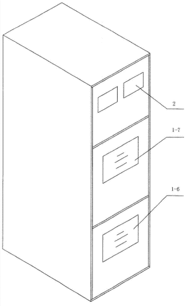
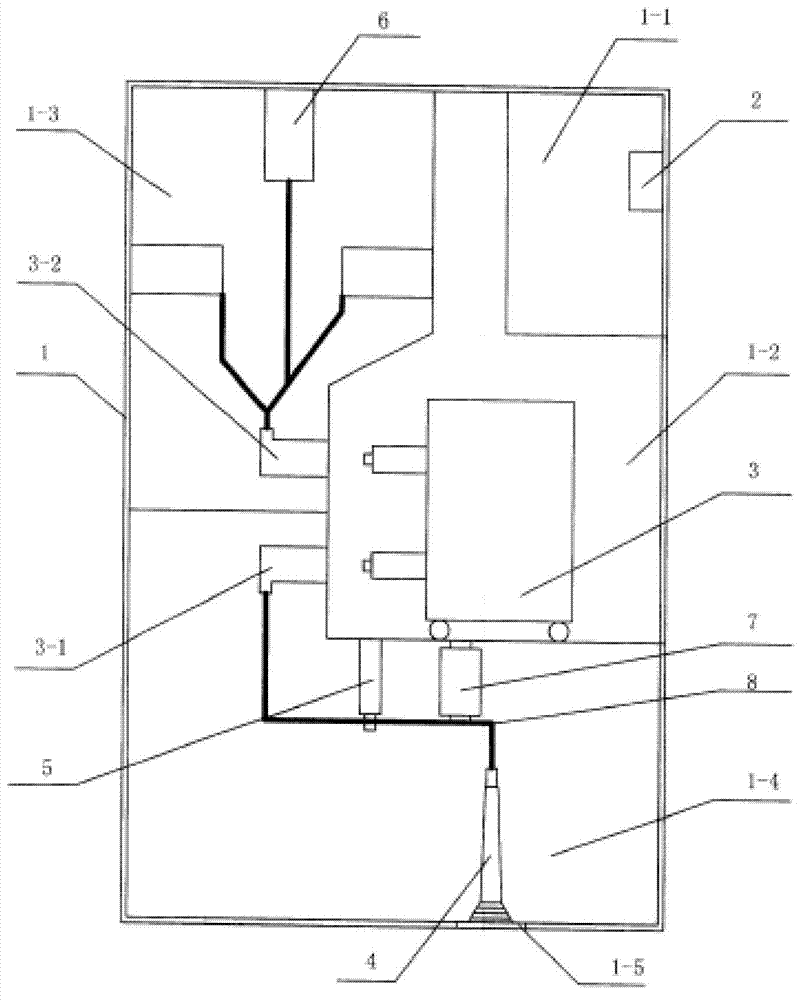
[0020] see figure 1 and figure 2 . The middle-mounted high-voltage switchgear of the present invention includes a metal cabinet 1 , a control instrument 2 and a circuit breaker 3 . The metal cabinet 1 is provided with a low-voltage room 1-1, a circuit breaker room 1-2, a bus room 1-3 and a cable room 1-4; the low-voltage room 1-1 is set at the upper front end of the metal cabinet 1, and the control instrument 2 Installed on the cabinet door of the low-voltage room. The circuit breaker chamber 1-2 is arranged in the middle part of the front end of the metal cabinet body 1, and the circuit breaker 3 is installed in the circuit breaker chamber 1-2, and an observation window 1-7 is opened on the cabinet door of the circuit breaker chamber 1-2. Behind the low-voltage room 1-1 and the circuit breaker room 1-2 is the busbar room 1-3. The busbar insulator 6 is installed in the busbar room 1-3, and the incoming busbar is fixed on the busbar insulator 6. The incoming busbar is conne...
Embodiment 2
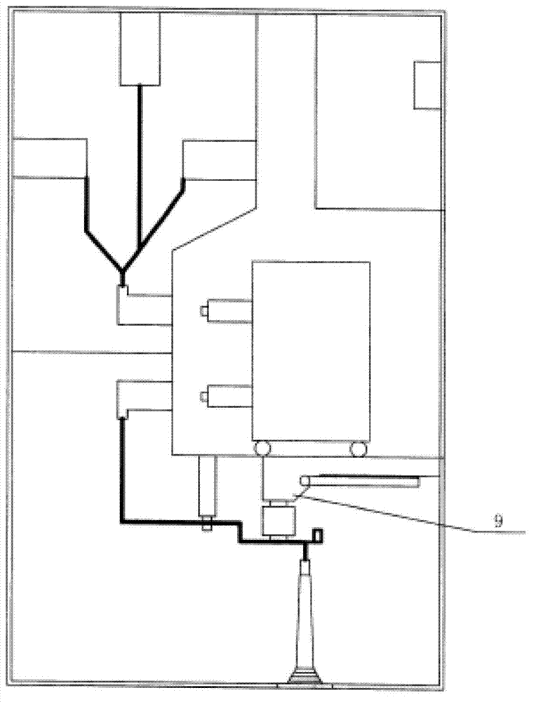
[0023] see image 3 . The difference between embodiment 2 and embodiment 1 is that the place where the insulator 7 is installed on the top partition of the cable room 1-4 is the earthing switch 9 installed, and the insulator that the earthing switch 9 itself has is connected on the busbar 8. The operator can conveniently observe the working state of the high-voltage cable 4 and the opening and closing state of the grounding switch 9 through the observation windows 1-6 in front of the cabinet; conveniently perform electrical tests on the high-voltage cable 4 and the grounding switch 9 in front of the cabinet.
Embodiment 3
[0025] see Figure 4 . Embodiment 3 differs from Embodiment 1 and Embodiment 2 in that, in addition to the grounding switch 9 being installed in the cable room, a current transformer 10 and a voltage transformer 11 are also installed, and the current transformer 10 and the voltage transformer 11 are installed In the middle and back of the cable room 1-4; the high-voltage cable 4 is first connected in series with the current transformer 10 through the horizontal busbar 8, and then connected in parallel with the voltage transformer 11, and then connected to the lower contact of the circuit breaker room 1-2 box 3-1. Operators can conveniently observe the working status of high-voltage cables 4, current transformers 10, voltage transformers 11 and the opening and closing status of grounding switches 9 through observation windows 1-6 in front of the cabinet; 4 and electrical test of current transformer 10, voltage transformer 11 and grounding switch 9.
PUM
 Abstract
Description
Claims
Application Information
 - R&D
- Intellectual Property
- Life Sciences
- Materials
- Tech Scout
- Unparalleled Data Quality
- Higher Quality Content
- 60% Fewer Hallucinations
Browse by: Latest US Patents, China's latest patents, Technical Efficacy Thesaurus, Application Domain, Technology Topic, Popular Technical Reports.
© 2025 PatSnap. All rights reserved.Legal|Privacy policy|Modern Slavery Act Transparency Statement|Sitemap|About US| Contact US: help@patsnap.com


