Cooling structure of rain-proof frequency conversion generator group

A technology for cooling structures and generator sets, which is applied to electric components, cooling/ventilation devices, electrical components, etc., can solve the problems of affecting the heat dissipation effect, small cross-section of the air duct, reducing the service life of the inverter, etc., to improve the assembly process. The effect of increasing the air duct cross section and prolonging the service life

Inactive Publication Date: 2013-01-30
SHANGHAI LIGER POWER TECH
View PDF6 Cites 0 Cited by
  • Summary
  • Abstract
  • Description
  • Claims
  • Application Information

AI Technical Summary

Problems solved by technology

[0004] This structure has the following disadvantages: First, because the air outlet of the motor casing directly blows to the rear cover of the panel, the hot air is blown into the inverter, which shortens the life of the inverter and reduces its reliability; The air guide connector of the device is directly fastened to the rack by screws, resulting in poor assembly process
It is not easy to disassemble; the third is because the cross section of the original air duct is too small and the seal is not good
Unable to guarantee enough cooling air for the inverter controller
It is not conducive to the timely and effective transfer of the heat generated by it, which affects the heat dissipation effect, thereby reducing the service life of the inverter; Fourth, because the air inlet is on the side of the machine, there is rainwater entering, resulting in hidden dangers of unit failure

Method used


Image

  • Cooling structure of rain-proof frequency conversion generator group
  • Cooling structure of rain-proof frequency conversion generator group
  • Cooling structure of rain-proof frequency conversion generator group

Examples


Embodiment Construction

[0016] Below in conjunction with accompanying drawing and specific embodiment the present invention is described in further detail:

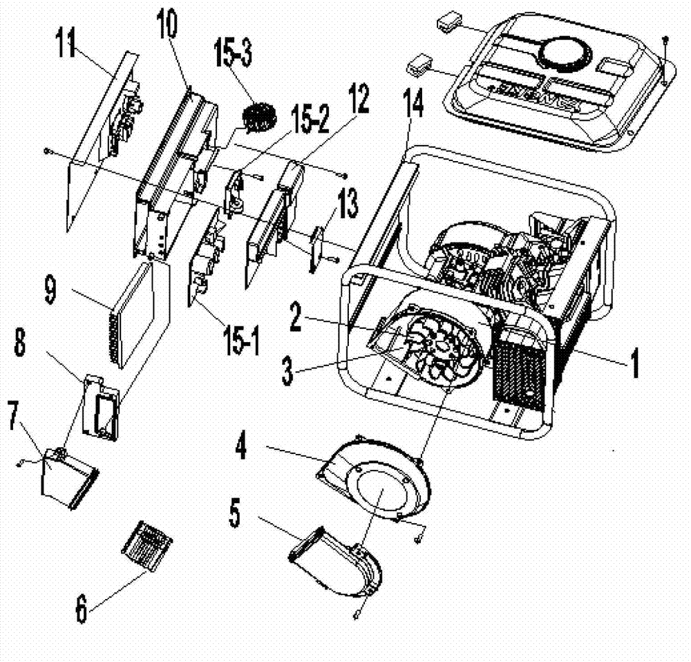
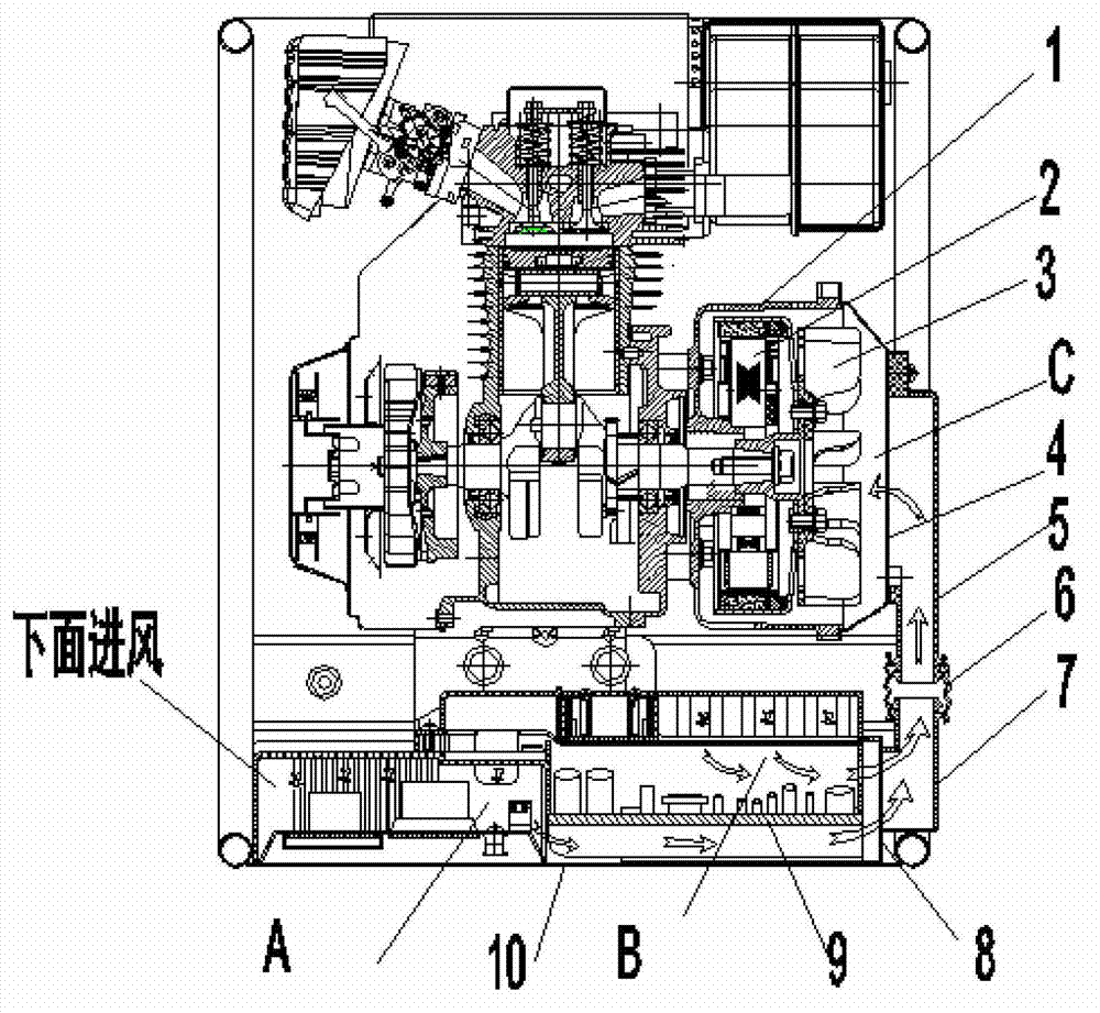
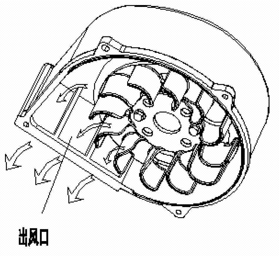
[0017] Depend on figure 1 , figure 2 , image 3 , Figure 4 It can be seen that the present invention includes: an installation box, an inverter controller, a control panel 11, a first hose 6, a turbine shell 1, a turbine cover 4, a generator 2, and wind blades 3; the installation box includes: an inverter Installation box 10, back cover 12, rainproof cover plate 13, connecting body 8 and inverter wind guide joint 7; Described installation box and control panel 11 are fixed on the frame 14; Described inverter controller comprises: Variable unit 15-1, electric regulator 15-2 and inductance 15-3; the inverter controller is fixed on the inverter installation box 10; The inverter installation box 10 is connected; the heat sink 9 and the control panel 11 form the first cooling and ventilation folder A; the rear cover 12 and the rainproof cover 1...


PUM


Abstract

The invention relates to a cooling structure of a rain-proof frequency conversion generator group. The cooling structure comprises an installation box, an inversion controller, a control panel, a first hose pipe, a turbine shell, a turbine cover plate, a generator and a fan blade, wherein the installation box comprises an inverter installation box, a rear cover, a rain-proof cover plate, a connecting body as well as an inverter air guide joint; the installation box and the control panel are fixed on a machine frame, the inversion controller comprises an inversion unit, an electric control device as well as an inductor, and is fixed on the inverter installation box; the inverter air guide joint is connected with the inverter installation box through the connecting body; and a cooling fin and the control panel form a first cooling blast clamping cavity; the rear cover and the rain-proof cover plate are fixed on the inverter installation box so as to form a second cooling blast clamping cavity; the generator and the fan blade are arranged in the turbine shell, and the generator, the fan blade and the turbine cover plate form a third cooling blast clamping cavity; and an air outlet of the turbine shell is separated from the inversion controller in a staggering manner, hot air is avoided contacting with the inversion controller, and the reliability of the inversion controller is guaranteed.

Description

technical field [0001] The invention relates to a variable frequency generating set, in particular to a cooling structure of the variable frequency generating set. Background technique [0002] With the improvement of people's living standards, people's requirements for the functional diversity of generator set products are also getting higher and higher. [0003] Chinese Patent No. 201020565125.6 discloses a cooling system for a variable frequency generator set. [0004] This structure has the following disadvantages: First, because the air outlet of the motor casing directly blows to the rear cover of the panel, the hot air is blown into the inverter, which shortens the life of the inverter and reduces its reliability; The air guide connector of the device is directly fastened to the frame by screws, which leads to poor assembly process. It is not easy to disassemble; the third is that the cross-section of the original air duct is too small and the seal is not good. The...

Claims


Application Information

Patent Timeline
Patent Type & Authority Applications(China)
IPC IPC(8): H02K9/04
Inventor 黄长明夏永胜丁如华
Owner SHANGHAI LIGER POWER TECH
Why Eureka
Try Eureka