Brake system and electromagnetic actuation device for same

A braking system, electromagnetic actuation technology, applied in the direction of brake type, energy absorption brake, asynchronous inductive clutch/brake, etc., can solve the problems of leakage, long production cycle, complex process and so on

Active Publication Date: 2013-01-30
COMAC +1
View PDF7 Cites 5 Cited by
  • Summary
  • Abstract
  • Description
  • Claims
  • Application Information

AI Technical Summary

Problems solved by technology

[0003] Yet above-mentioned no matter aircraft brake system or automobile brake system all have inherent shortcoming
For example, for aircraft hydraulic brake systems, problems such as inherent leakage, poor anti-pollution ability, relatively low dispatch rate, and complicated maintenance have not been resolved
[0005] 1) The loss of the brake disc as a consumable is huge. Every 200-600 landing sorties, the brake disc needs to be replaced, which increases the cost of use;
[0006] 2) The manufacturing process of friction materials is complex and the production cycle is long. Taking carbon-carbon composite materials as an example, the production cycle of a pair of brake discs is at least 3 months;
[0007] 3) The powder metallurgy / metal brake disc is heavy, and it is easy to bond at high temperature, and it is easy to produce cracks and blocks;
[0008] 4) Carbon-carbon composite materials have low strength, large volume, small static friction coefficient, complex process and high cost

Method used


Image

  • Brake system and electromagnetic actuation device for same
  • Brake system and electromagnetic actuation device for same
  • Brake system and electromagnetic actuation device for same

Examples


Embodiment Construction

[0029] As required, specific embodiments of the invention will be disclosed herein. However, it should be understood that the embodiments disclosed herein are merely typical examples of the invention, which can be embodied in various forms. Therefore, specific details disclosed herein are not to be considered limiting, but merely as a basis for the claims and as a representative basis for teaching one skilled in the art to variously employ the invention in any appropriate way in practice, This includes taking various features disclosed herein and combining features that may not be expressly disclosed herein.

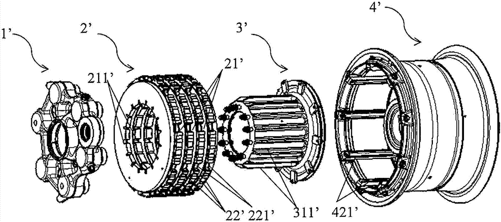
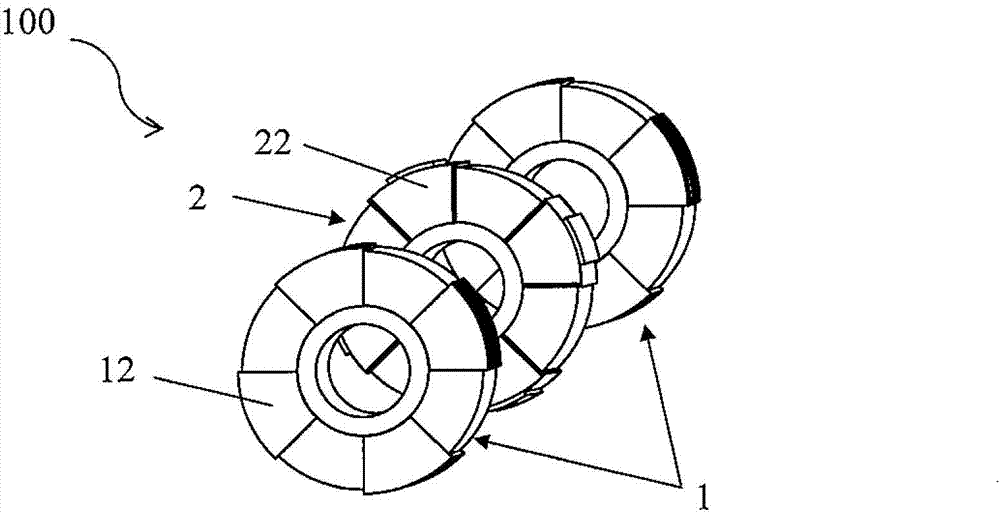
[0030] and figure 1 Compared with the mechanical parts of the traditional hydraulic brake system or electric brake system shown, the brake system according to the preferred embodiment of the present invention omits the hydraulic or electric drive actuator 1' and the brake disc 2', and introduces an improved Type electromagnetic actuator 100 (such as figure 2 shown). ...


PUM


Abstract

The invention relates to the field of brake systems and provides an electromagnetic actuation device suitable for a brake system. The electromagnetic actuation device comprises at least two fixed disks and at least one movable disk. The fixed disks are coaxial with the movable disks. Each movable disk is located between two adjacent fixed disks. Pairs of fixed disk iron cores are circumferentially disposed at intervals on each fixed disk. A fixed disk coil is wound on each fixed disk iron core. Each fixed disk coil is connected to an external power supply in a parallel manner. When the fixed disk coils are powered, polarity of two adjacent fixed disk iron cores is opposite and a magnetic field along different directions and perpendicular to a plane on which each fixed disk is positioned is generated. Movable disk iron cores corresponding to positions and number of the fixed disk iron cores are disposed on the movable disks. A movable disk coil is wound on each movable disk iron core along a radial direction of each movable disk. The movable disk coils are connected to external charging/power-utilizing parts. When the fixed disk coils are powered to generate magnetic fields and during rotation of the movable disks, induced current and electromagnetic fore which prevent the movable disks from rotating are generated in movable disk coils which emit heat, and kinetic energy needs to be overcome by the brake system is converted into electric energy, electromagnetic energy and heat energy.

Description

technical field [0001] The present invention relates to brake technology, more specifically to a brake system and an electromagnetic actuating device suitable for the brake system. Background technique [0002] Cars and airplanes, which are the main means of transportation today, all have brake systems for deceleration and braking. Among them, the brake system of the car mainly relies on the friction of the brake disc to achieve braking. The aircraft braking system is mostly a hydraulic braking system or an electric braking system. Such as figure 1 As shown, the hydraulic brake system or electric brake system includes a hydraulic or electric drive actuator 1', a brake disc 2', a torque tube 3' and a hub 4', wherein the brake disc 2' includes a fixed disc 21' and a moving disc 22 ', through the cooperation of the inner keyway 211' on the fixed plate 21' and the outer key 311' on the torque cylinder 3', the fixed plate 21' is set on the torque cylinder 3', and at the same t...

Claims


Application Information

Patent Timeline
Patent Type & Authority Applications(China)
IPC IPC(8): H02K49/04F16D61/00
Inventor 肖扬陆清任碧诗王鸿鑫陆波黄喜平陈诚姜逸民
Owner COMAC
Why Eureka
Try Eureka