Pulse device system

A technology of stamping device and loader, applied in the direction of presses, manufacturing tools, etc., can solve the problems of sliding accident product thickness and enlargement, and achieve the effect of preventing sliding accidents and suppressing uneven thickness

Active Publication Date: 2013-01-30
KITAGAWA SEIKI
View PDF10 Cites 2 Cited by
  • Summary
  • Abstract
  • Description
  • Claims
  • Application Information

AI Technical Summary

Problems solved by technology

As a result, problems such as sliding accidents and uneven thickness of the product may occur

Method used


Image

  • Pulse device system
  • Pulse device system
  • Pulse device system

Examples


Embodiment Construction

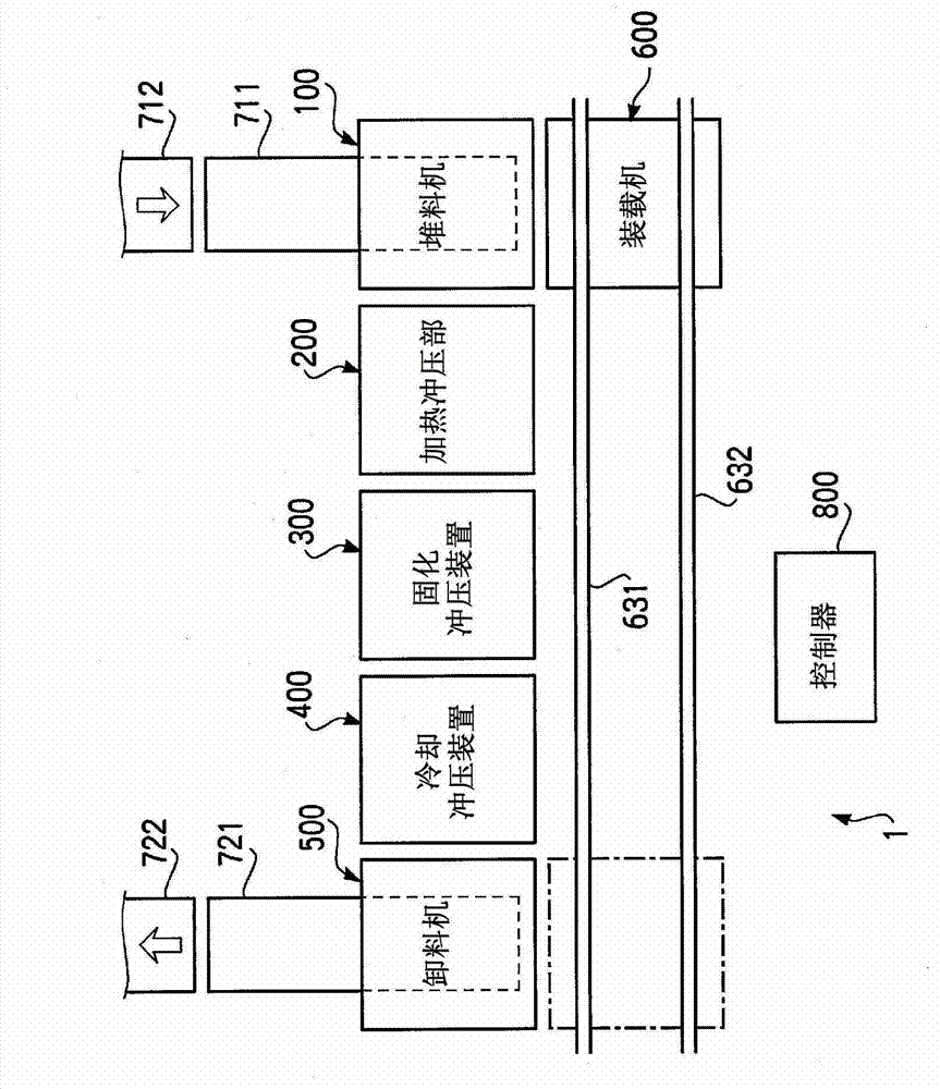
[0024] Hereinafter, embodiments of the present invention will be described in detail using the drawings. figure 1 It is a block diagram showing the whole of the press machine system 1 of this embodiment. The press device system 1 of the present embodiment includes: a stocker 100 for temporarily storing a workpiece before forming; a heating press unit 200 for heating and pressing the workpiece; ) solidification stamping device 300; cooling stamping device 400 for cooling and solidifying the workpiece after stamping; unstacker 500 for temporarily storing the processed workpiece after cooling stamping; 200 . The loader 600 for transporting the workpiece between the solidification press device 300 , the cooling press device 400 , and the unloader 500 . In addition, an assembly section (not shown) for producing a workpiece formed by alternately stacking a plurality of prepregs and copper foil sheets is arranged upstream of the stacker 100, and the workpiece produced by the assembl...


PUM


Abstract

The disclosed pulse device system is characterized by having: a plurality of heating pulse devices that sandwich a processed object between heating plates and apply heating pulses; a loader that carries the processed object into and out of the plurality of heating pulse devices; and a control means that controls the plurality of heating pulse devices and the aforementioned loader. The pulse device system is further characterized by the control device controlling the aforementioned loader and another heating pulse device while heating pulses are applied to the processed object by one of the plurality of heating pulse devices, and carries the processed object into and out of the other heating pulse device.

Description

technical field [0001] The present invention relates to a press device system provided with a heating press device for heating and pressing a workpiece under vacuum in a vacuum chamber. Background technique [0002] As a method of manufacturing an electronic circuit board, there is a method of using a heated press device to press a workpiece formed by alternately laminating resin sheets such as prepreg sheets and copper foil between hot plates. At this time, since the time required for hot stamping is several times longer than the formation (assembly) time for forming a workpiece based on lamination, the hot stamping device is described in Japanese Patent Application Laid-Open Publication JP2002-316296A (hereinafter referred to as the patent document). As described in 1), multiple workpieces can be punched at one time using a multi-stage press device that arranges a plurality of hot plates in the vertical direction, and the workpiece can be formed efficiently without stoppin...

Claims


Application Information

Patent Timeline
IPC IPC(8): B30B15/34B30B7/02B30B12/00B30B15/30B30B15/32
CPCB30B15/30B30B15/34B30B12/00B30B15/32B30B15/064B30B7/02B30B7/023
Inventor 冈崎静明
Owner KITAGAWA SEIKI
Why Eureka
Try Eureka