Method of manufacturing tubular member for exhaust gas treatment device, and coating film forming device

Pending Publication Date: 2022-09-15
NGK INSULATORS LTD
View PDF0 Cites 0 Cited by
  • Summary
  • Abstract
  • Description
  • Claims
  • Application Information

AI Technical Summary

Benefits of technology

The invention aims to improve the quality of tubular members with an insulating layer. The goal is to reduce thickness unevenness in the layer.

Problems solved by technology

However, the coating liquid for insulating layer formation drips when applied, and hence thickness unevenness in the insulating layer to be obtained occurs to make the quality of the insulating layer poor in some cases.

Method used


Image

  • Method of manufacturing tubular member for exhaust gas treatment device, and coating film forming device
  • Method of manufacturing tubular member for exhaust gas treatment device, and coating film forming device
  • Method of manufacturing tubular member for exhaust gas treatment device, and coating film forming device

Examples


Embodiment Construction

[0020]Embodiments of the present invention are described below with reference to the drawings. However, the present invention is not limited to these embodiments.

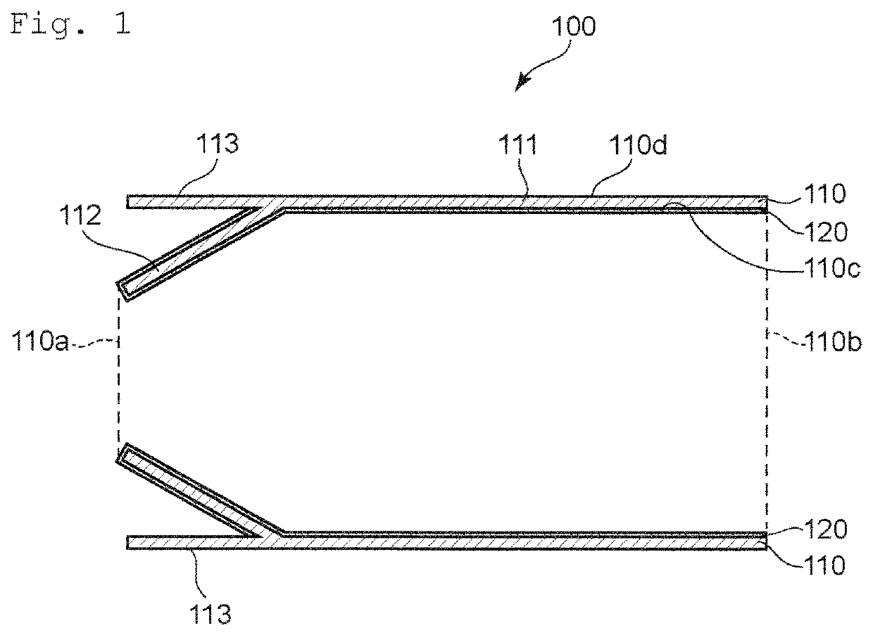
[0021]FIG. 1 is a sectional view for illustrating the schematic configuration of a tubular member to be used in an exhaust gas treatment device according to at least one embodiment of the present invention. A tubular member 100 includes a tubular main body 110 made of a metal and an insulating layer 120 formed on the tubular main body 110.

[0022]The tubular main body 110 has a straight portion 111 of a cylindrical shape and a reduced diameter portion 112 whose inner diameter is continuously reduced toward a first end surface 110a side (left side or upstream side in FIG. 1). In addition to such reduced diameter portion, for example, another member (not shown) may be combined to form a complicated structure. Specifically, an extending portion 113 extending on the first end surface 110a side is formed on the end portion of the ...


PUM


Abstract

A method of manufacturing a tubular member for an exhaust gas treatment device according to at least one embodiment of the present invention, the tubular member including a tubular main body made of a metal and an insulating layer formed on at least an inner peripheral surface of the tubular main body, the insulating layer containing glass, includes steps of: forming a coating film by spraying a coating liquid for insulating layer formation onto the inner peripheral surface of the tubular main body; and firing the coating film to obtain the insulating layer. The spraying is performed while the tubular main body is rotated with a length direction thereof being a rotation axis.

Description

CROSS-REFERENCE TO RELATED APPLICATION[0001]The present application claims priority from Japanese Application JP 2021-41347 filed on Mar. 15, 2021, the content of which is hereby incorporated by reference into this application.BACKGROUND OF THE INVENTION1. Field of the Invention[0002]One or more embodiments of the present invention relate to a method of manufacturing a tubular member for an exhaust gas treatment device, and to a coating film forming device.2. Description of the Related Art[0003]A catalyst support obtained by causing a support to support a catalyst is used for treatment of a harmful substance in an exhaust gas discharged from a vehicle engine. In this case, there is a problem in that, when a temperature of the catalyst is low at a start of the engine, the temperature of the catalyst is not increased to a predetermined temperature, resulting in a failure to sufficiently purify the exhaust gas. In order to solve such problem, progress is being made in development of an...

Claims


Application Information

Patent Timeline
IPC IPC(8): B05D3/02F01N13/14B05D1/00B05D1/02
CPCB05D3/0254F01N13/148F01N13/141B05D1/005B05D1/02B05B13/0663B05B16/20F01N3/2828F01N3/2842C23D5/005C23D5/02F01N3/2013B05B13/0228B05B13/0654B05B13/041
Inventor FUJIMURA, RYOKATO, KODAINISHIO, AKIFUMI
Owner NGK INSULATORS LTD
Why Eureka
Try Eureka